2 set-up mode, 3 auto/manual mode, 4 loading the feed – PA Industries Magnum Servo Roll Feed SRF-M12/18/24/32/36/48 - Installation and Operating Instructions User Manual
Page 7
7
choose between ‘
PRESS-BEFORE-FEED
’ (
PBF
)
and ‘
FEED-BEFORE-PRESS
’ (
FBP
) operating mode.
When ‘
PBF’
mode is selected and the ‘
CYCLE
START
’ button is pressed on the control panel, the
feeder causes the ‘
AUTO
’ and ‘
PERMIT PRESS
’
relays to turn on thus enabling the start of
continuous cycling on the press.
When ‘
FBP
’ is selected and the ‘
CYCLE START
’
button is pressed on the feed control, the material/
strip will be fed forward the programmed pitch
before the press is started. The Operator may verify
that the strip is in position before starting the press.
The Magnum Servo Roll Feed will now follow the
press until it is stopped by the Operator, counter,
emergency stop, or feed error.
5.2 SET-UP MODE
‘
SET-UP MODE
’ is used primarily during the threading
of the strip through the die. This mode allows the
‘
JOG-TO-FEED
’
Length operations to be performed.
While in ‘
SET-UP MODE’
, the strip may be moved
using the ‘
JOG FORWARD
’ operator button. If
the ‘
JOG FORWARD
’ is stopped before the ‘
FEED
LENGTH’
is reached, then either the ‘
JOG FOR-
WARD
’, or ‘
JOG REVERSE
’ operator buttons will
work. The ‘
JOG REVERSE
’ will not allow the
strip to go backwards beyond the initial ‘
FEED
LENGTH’
starting point. The ‘
JOG FORWARD
’
operator button will function until the end of the
‘
FEED LENGTH’
is reached.
During ‘
SET-UP MODE
’, the bottom line on the
display will show ‘
WAITING FOR JOG
’. When the
‘
FEED LENGTH
’ is reached, the jog buttons become
in active and the message on the display will show
‘
WAITING FOR PRESS
’. The jog buttons will not
become active again until after the press has made a
cycle
.
5.3 AUTO/MANUAL MODE
‘
AUTO MODE
’ is used for production running of
the Edge Servo Roll Feed. When ‘
AUTO
’ is selected
via the 2-position selector switch, the control is put
into ‘
MANUAL MODE
’ until the ‘
CYCLE START
’
button is pressed. During manual mode, the feeder
may be jogged infinitely in either direction. After
the ‘
CYCLE START
’ button is pushed, the jog
buttons are inactive, and the feeding of the strip
follows the cam signals from the press. During
‘
AUTO MODE
’, the control keeps check on
synchronization of the feeder and press. If the
Feeder does not complete the index within the feed
cam window, the message ‘
SYNC FAULT
’ displays.
The Magnum Servo Roll Feed has (2) modes of
automatic cycling. The feeder can operate with
‘
SINGLE STROKE
’ or ‘
CONTINUOUS PRESS
MODE
’. The mode is selected through an input to the
feed controller. The press single stroke/continuous
mode switch should be interfaced to this input for
proper operation. During ‘
SINGLE STROKE
’
mode operation, the ‘
PERMIT PRESS
’ output relay
is activated upon the completion of each feed index.
The ‘
PERMIT PRESS OUTPUT RELAY
’ remains
active until the continue cam signal turns on. The
‘
PERMIT PRESS OUTPUT RELAY
’ may be used
to signal the press when to initiate the single stroke
cycle. The automatic cycling of the press and feeder
will continue until the batch is completed, or the
cycle is stopped by the operator, or an error occurs.
During ‘
CONTINUOUS PRESS MODE
’, the
‘
PERMIT PRESS OUTPUT RELAY
’ turns on at the
beginning of the indexing. The ‘
PERMIT PRESS
RELAY
’ remains active until the automatic cycling
is stopped by either ‘
CYCLE STOP
’, ‘
BATCH
COMPLETE
’, ‘
SYNC FAULT
’, or any other drive
related error. Under ‘
CYCLE STOP
’ or ‘
BATCH
COMPLETE
’ stopping, the output will turn off at
the beginning of the ‘
FEED CAM SIGNAL
’. This
should allow the press to stop near the top of the
stroke. Under ‘
SYNC FAULT
’ or other drive fault
conditions, the ‘
PERMIT PRESS RELAY
’ will turn
off immediately upon detection of the error.
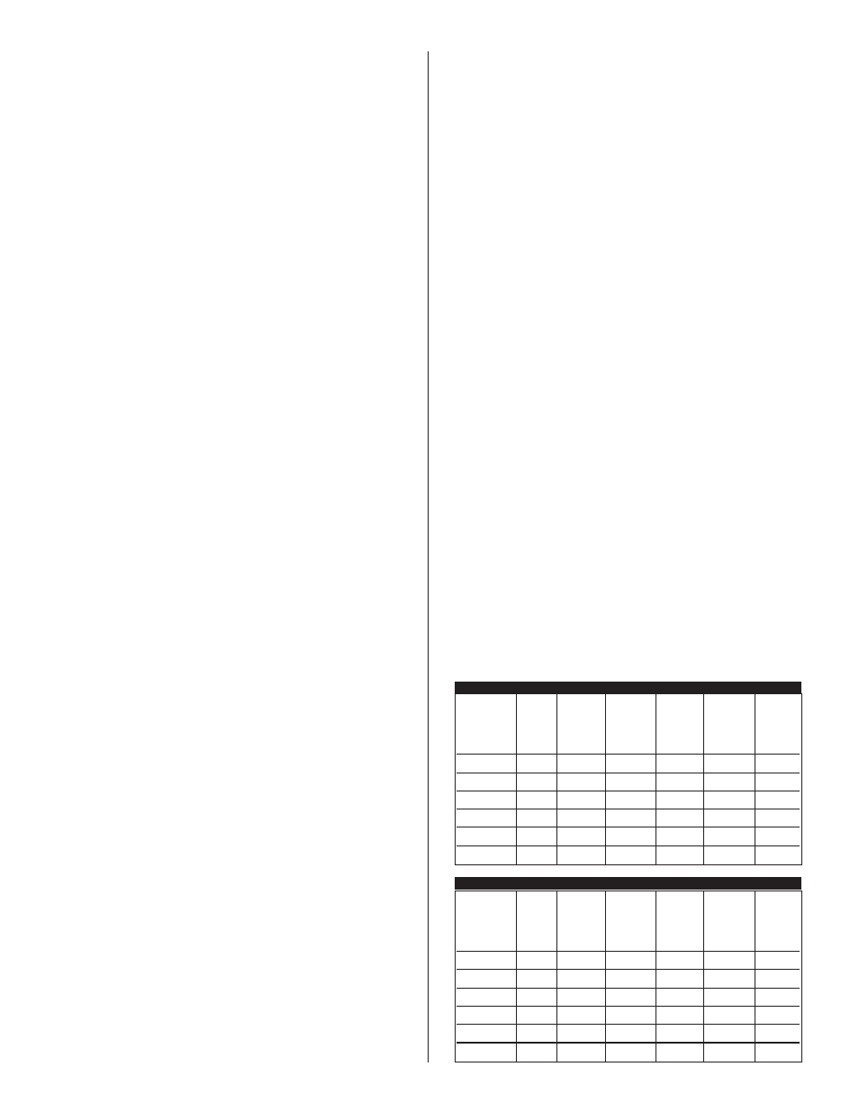
5.4 LOADING THE FEED
The material thickness and width table below defines
the maximum stock thickness at full width allowed.
It also defines the maximum material speed and
cycles per minute (CPM). Do not try to operate the
feeder with material thicker than it was deigned to
feed. READ THIS TABLE BEFORE LOADING
ANY MATERIAL INTO THE FEEDER.
MILLIMETERS
Max.
Max.
Stock
Cross
Max.
Max.
Max.
Thick.
Section Material
Max.
Stock
Stock
At Full
Area
Speed
Feed
Model
Width
Thick.
Width
Sq. In.
Ft./Min.
C.P.M.
SRF-M12
12.0
.250
.200
2.4
315
600
SRF-M18
18.0
.250
.187
3.4
315
600
SRF-M24
24.0
.250
.164
4.0
315
600
SRF-M32
32.0
.250
.136
4.3
315
600
SRF-M36
36.0
.250
.125
4.5
315
600
SRF-M48
48.0
.250
.094
4.5
315
600
Max.
Max.
Stock
Cross
Max.
Max.
Max.
Thick.
Section Material
Max.
Stock
Stock
At Full
Area
Speed
Feed
Model
Width
Thick.
Width
Sq. mm
M/Min.
C.P.M.
SRF-M12
305
6.3
5.1
1550
96
600
SRF-M18
457
6.3
4.7
2200
96
600
SRF-M24
610
6.3
4.2
2600
96
600
SRF-M32
813
6.3
3.4
2800
96
600
SRF-M36
914
6.3
3.2
2900
96
600
SRF-M48
1220
6.3
2.4
2900
96
600
INCHES