Dialight HBxxMx DuroSite LED High Bay User Manual
Page 3
Document No: 9100-127-1327-99 Rev R
Page 3 of 12
1501 Route 34 South, Farmingdale, NJ 07727
Tel: (732) 919-3119 Fax: (732) 751-5778
www.dialight.com
Dialight de México S.R.L de C.V. Calle Lirios s/n
Col. Carlos Pacheco, Ensenada Baja California, México C.P. 22830
+52 (646) 156-70-80
Pendent Mount Installation Steps:
For maximum long term reliability and light output, the light must be installed in free air.
o
The High Bay fixture design incorporates an over-temperature control circuit that
reduces input power should internal temperatures reach a maximum level. As a
result, light output may be reduced.
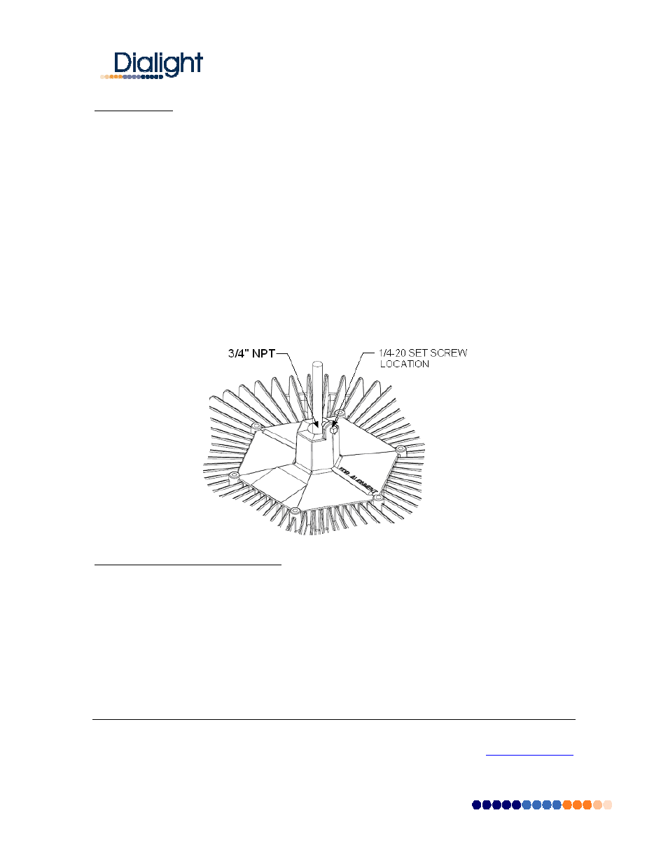
The High Bay fixture is threaded for 3/4” NPT in order to be assembled to conduit.
o
Calculate and measure required conduit length.
o
Feed the power cable through the conduit and into the junction box.
o
Attach the fixture to the conduit (using Teflon tape or pipe sealant).
o
Insert 1/4-20 anti-rotation screw in order to secure the fixture to the conduit.
o
Note: For model numbers HB6xxx and HB7xxx only, alignment bar on top of fixture
corresponds to major axis of the “narrow oval” light pattern.
Connect power cable conductors as follows:
o
Green wire connects to Safety Ground.
o
White wire connects to Neutral
o
Black wire connects to Live
Restore power and verify operation.
Interfacing to an Occupancy Sensor:
The Dialight High Bay fixture is ideally suited for control by an external occupancy sensor (not
provided by Dialight) in order to maximize energy savings based on its instant-on behavior and low
power consumption. Instructions for connecting the High Bay fixture to an occupancy sensor are
listed below.
WARNING: TO BE INSTALLED AND/OR USED IN ACCORDANCE WITH APPROPRIATE
ELECTRICAL CODES AND REGULATIONS.
WARNING: CONTROLLING A LOAD IN EXCESS OF THE SPECIFIED RATINGS OF THE
OCCUPANCY SENSOR COULD DAMAGE THE UNIT AND POSE RISK OF FIRE, ELECTRIC