Dialight RTOxxxxxx Vigilant L-810 RTO Red LED Obstruction Lights User Manual
Dialight Lighting
Document No: 9100-127-1231-99
Issued: November, 2011
Sheet 1 of 2
INSTALLATION INSTRUCTIONS and PARTS LIST
SINGLE, DUAL and RETRO FIXTURES
MINI L-810 OBSTRUCTION LIGHT
-------------------------------------------------------------------------------------------------------------------------------------------
-------------------------------------------------------------------------------------------------------------------------------------------
1501 Route 34 South, Farmingdale, NJ 07727 Tel: [732] 919-3119 Fax: [732] 751-5778 www.dialight.com
Model No
Description
Model No
Description
Model No
Description
RTO 1x07 xxx
120-240 VAC, FAA
RTO 6x07 xxx
120-240 VAC, Canada
RTO 0x07 xxx
120-240 VAC, NonFAA
RTO 1x06 xxx
277 VAC
RTO 1x08 xxx
12-48 VDC
RTO 2x07 xxx
120-240 VAC, C1D2
RTO BW07 xxx
120-277 VAC
RTO CR07 xxx
120-240 VAC, IR
RTO CR08 xxx
12-48 VDC, IR
RTO 1R18 xxx
12-48 VDC
RTO 6CR7 xxx
120-240 VAC, Canada IR
5th digit ... x = color last 3 digits ... 001 = Single 002 = Dual 004 = Retro
WARNING:
DE-ENERGIZE CIRCUIT BEFORE INSTALLING OR WORKING ON FIXTURE
The light assembly fixture can be mounted in any position. When mounted 'upright' [as illustrated] the fixture will meet the
designed optical specifications for Aircraft Obstruction Warnings. When mounted in any other position, the fixture will not
meet the designed optical specifications mentioned and will be considered as a visual signal fixture.
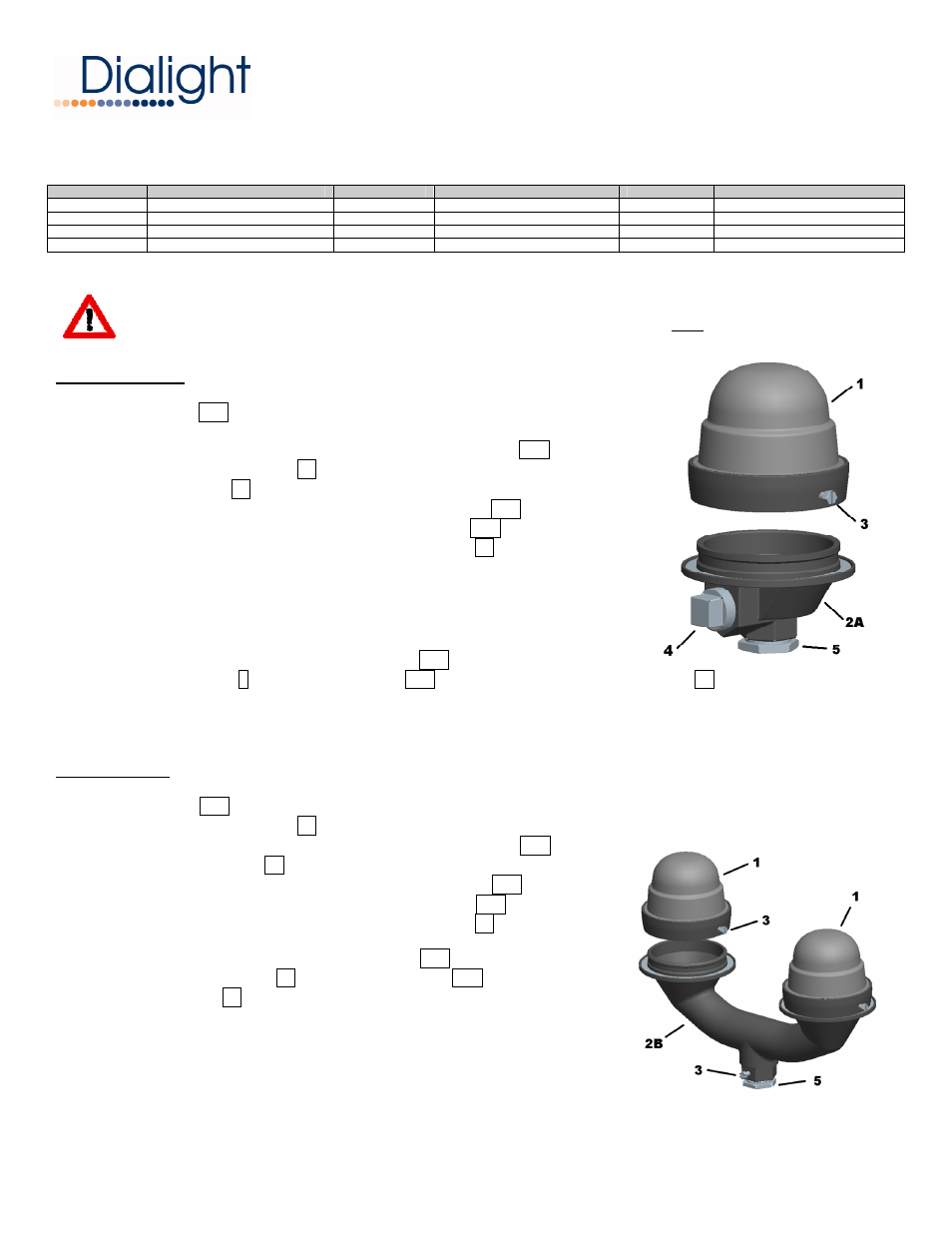
SINGLE FIXTURE INSTALLATION STEPS:
► The wire housing 2A has a 1” NPT [3/4" bushing] end to be assembled to
conduit [right angle or vertical]
Use a 1-1/2” wrench to tighten and attach the wire housing 2A to the conduit
Remove reducing bushing 5 if threading into 1” NPT conduit
Use 1” NPT plug 4 to close threaded opening not being used
► Feed the supply wires through the conduit and wire housing 2A leaving
approx 6” of wire for termination inside the wire housing 2A .
► Electrically connect the supply wires to the light assembly 1 wires
Connect the light assembly wire [with voltage label]
to the Hot AC line or Positive [+] line
Connect the light assembly wire [without label]
to the Neutral AC line or Negative [-] line
Connect the light assembly green grounding wire to the Ground line
► Tuck the connected wires inside the wire housing 2A .
► Position light assembly 1 over the wire housing 2A and secure using the holding screws 3 .
► Restore power and verify operation
DUAL FIXTURE INSTALLATION STEPS:
► The dual housing 2B has a 1” NPT end to be assembled to conduit
Remove reducing bushing 5 if threading into 1” NPT conduit
Use a 1-1/2” wrench to tighten and attach the dual housing 2B to the conduit
Tighten the 1/4 screw 3 to secure the dual wire housing in position
► Feed the supply wires through the conduit and dual housing 2B leaving
approx 6” of wire for termination inside the wire housing 2B .
► Electrically connect the supply wires to the light assembly 1 wires
same as SINGLE FIXTURE installation
► Tuck the connected wires inside the dual housing 2B .
► Position each light assembly 1 over the dual housing 2B and use
the holding screws 3 to secure the light assembly in place
► Restore power and verify operation