Dialight ATEX Red Obstruction Light User Manual
Dialight Lighting
Document No: 9100-127-1004-99 Rev. B
Issued: August 31, 2007
Sheet 1 of 5
INSTALLATION INSTRUCTIONS and PARTS LIST
ATEX Zone 2
L-810 OBSTRUCTION LIGHT [
SINGLE FIXTURE
]
120 and 230 VAC
-------------------------------------------------------------------------------------------------------------------------------------------
1501 Route 34 South, Farmingdale, NJ 07727 Tel: [732] 919-3119 Fax: [732] 751-5778 www.dialight.com
PART No:
860-9R01-001 [120V]
860-9R02-001 [230V]
WARNING:
DE-ENERGIZE CIRCUIT BEFORE INSTALLING OR WORKING ON FIXTURE
CAUTION
To retain seal integrity (and preserve warranty) do not loosen or remove the
clamp holding the light assembly together
REMOVAL OR LOOSENING OF THE CLAMP WILL VOID ALL WARRANTIES
If the light fixture is mounted in any position, other than upright, it will not meet
the designed light output specifications
Mounting the fixture in a position other than upright means that the light fixture is
now a visual signal fixture ** and not intended as an obstruction fixture
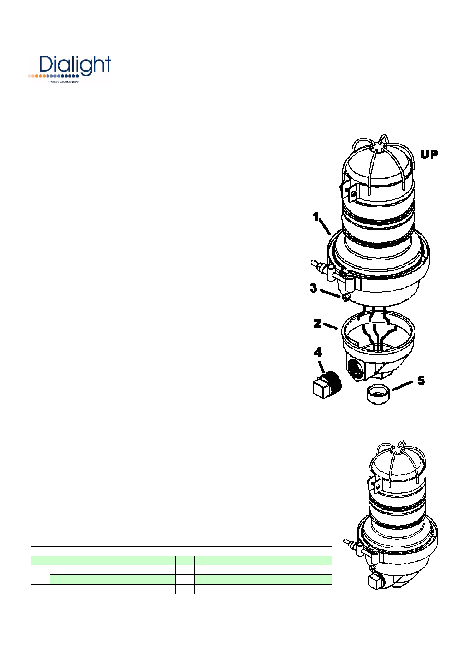
INSTALLATION STEPS:
•
The wire housing [2] has a 1” NPT [3/4" bushing] end to be assembled
to conduit … right angle or vertical
o
Use a 1-1/2” wrench to tighten and attach the wire housing [2]
to the conduit
o
Use 1” NPT plug [4] to close threaded opening not being used
o
Remove reducing bushing [5] if threading into 1” NPT conduit
•
Feed the supply wires through the conduit and wire housing [2] leaving
approx 6” of wire for termination inside the wire housing [2]
•
Electrically connect the supply wires to the light assembly [1] wires
o
Connect the light assembly wire (with voltage label) to
the Hot AC line
o
Connect the light assembly wire [without label] to
the Neutral AC line
o
Connect the grounding wire [from green screw] to the Ground line
•
Tuck the connected wires inside the wire housing [2]
•
Position light assembly [1] on the wire housing [2] and use the holding screws [3] to secure the light assembly in
place
** Units being installed as a visual signal as mentioned above, will require a continuous
bead of silicone sealing the gap between the base of the light assembly [1] and the housing [2]
•
Restore power and verify operation
Please refer to product data sheet for electrical parameters if required
U.S. Patent 6,425,678 *
Item Catalog No.
Description
Item Catalog No.
Description
860-9R01
Red Light Assy 120V Atex
3
---
1/4-20 x 1/2 Holding Screw
860-9R02
Red Light Assy 240V Atex
4
---
1" NPT Plug
2
860-1001
Wire Housing
5
---
1" to 3/4" Bushing
PARTS LIST
1