Dialight 860-xxxx Vigilant L-810 Red LED Obstruction Lights User Manual
Obstruction / visual signal light
Document No: 9100-127-1112-99 REV B
Issued: April 03, 2009
Sheet 1 of 2
OBSTRUCTION / VISUAL SIGNAL LIGHT
SINGLE and DUAL FIXTURES
INSTALLATION INSTRUCTIONS and PARTS LIST
1501 Route 34 South, Farmingdale, NJ 07727 USA Tel: [+1] 732-919-3119 Fax: [+1] 732-751-5778 www.dialight.com
PART No:
860-1x01-00x
120 VAC, Single or Dual
860-1x02-00x
240 VAC, Single or Dual
860-1x03-00x
12 VDC, Single or Dual
860-1x04-00x
48 VDC, Single or Dual
860-1x02-00x EU
230 VAC, Single or Dual, Europe
860-1x05-00x
24 VDC, Single or Dual
860-1x06-00x
10-27 VDC, Single or Dual
860-1R01-001-FAA
120 VAC, Single
860-3x03-00x
12 VDC, Single or Dual, Low Watt
860-4x02-00x
240 VAC, Single or Dual, 50 cd
860-4x02-00x EU
230 VAC, Single or Dual, Europe
860-5x02-00x
240 VDC, Single or Dual, 10 cd
860-6x01-001
120 VAC, Single or Dual, Canada
860-7X02-002
240 VDC, Dual, Australia
860-8x04-001
48 VDC, Single, Sweden
[last 3 digits ... 001 = Single 002 = Dual]
WARNING:
DE-ENERGIZE CIRCUIT BEFORE INSTALLING OR WORKING ON FIXTURE
CAUTION
To retain seal integrity (and preserve warranty) do not loosen or remove the clamp holding the light assembly together
REMOVAL OR LOOSENING OF THE CLAMP WILL VOID ALL WARRANTIES
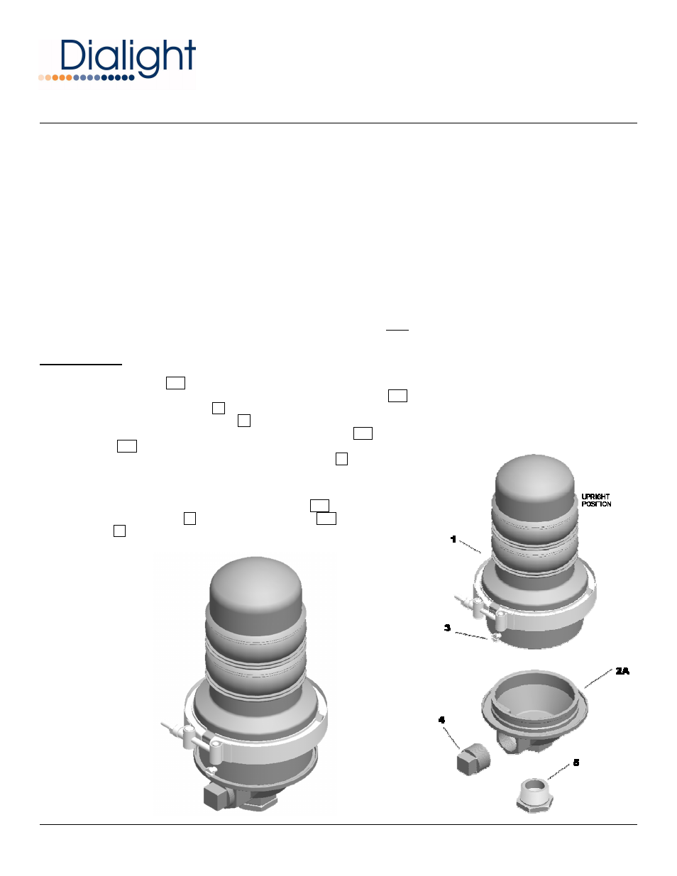
The light assembly fixture can be mounted in any position. When mounted 'upright' [as illustrated] the fixture will meet the designed
optical specifications for Aircraft Obstruction Warnings. When mounted in any other position, the fixture will not meet the designed
optical specifications mentioned and will be considered as a visual signal fixture.
SINGLE FIXTURE INSTALLATION STEPS:
•
The single housing 2A has a 1” NPT [3/4" bushing] end to be assembled to conduit … right angle or vertical
o
Use a 1-1/2” wrench to attach and tighten the single housing 2A to the conduit
o
Use the 1” NPT plug 4 to close threaded opening not being used
o
Remove reducing bushing 5 if threading into 1” NPT conduit
•
Feed the supply wires through the conduit and single housing 2A leaving approx 6” of wire for termination inside the single
housing 2A .
•
Electrically connect the supply wires to the light assembly 1 wires
o
Connect the light assembly wire (with voltage label) to the Hot AC or Positive [+] line
o
Connect the light assembly wire [without label] to the Neutral AC or Negative [-] line
o
Connect the grounding wire [from green screw] to the Ground line
•
Tuck the connected wires inside the single housing. 2A .
•
Position light assembly 1 on the wire single housing 2A and use the holding
screws 3 to secure the light assembly in place
•
Restore power and verify operation