Dialight SafeSite L-864 Red LED Class I, Div 2 Medium Intensity Beacon User Manual
Page 6
Document No.
9100-127-1438-99 Rev A
March 31, 2011
_____________________________________________________________________
_____________________________________________________________________________
Dialight Corporation 1501 Route 34 South Farmingdale NJ 07727
Tel: 732.919.3119 Fax: 732.751.5778 Web: www.dialight.com
6 of 13
Section 3: Operation and Test
Prior to installation, it is recommended that the unit be tested to ensure no
damage was incurred during shipping. This is accomplished by applying power to
the beacon. Visual verification of the functioning of the Beacon will indicate
proper performance.
Upon completion of this test, the installation may proceed.
Section 4: Beacon Theory of Operation
4.0 System Overview
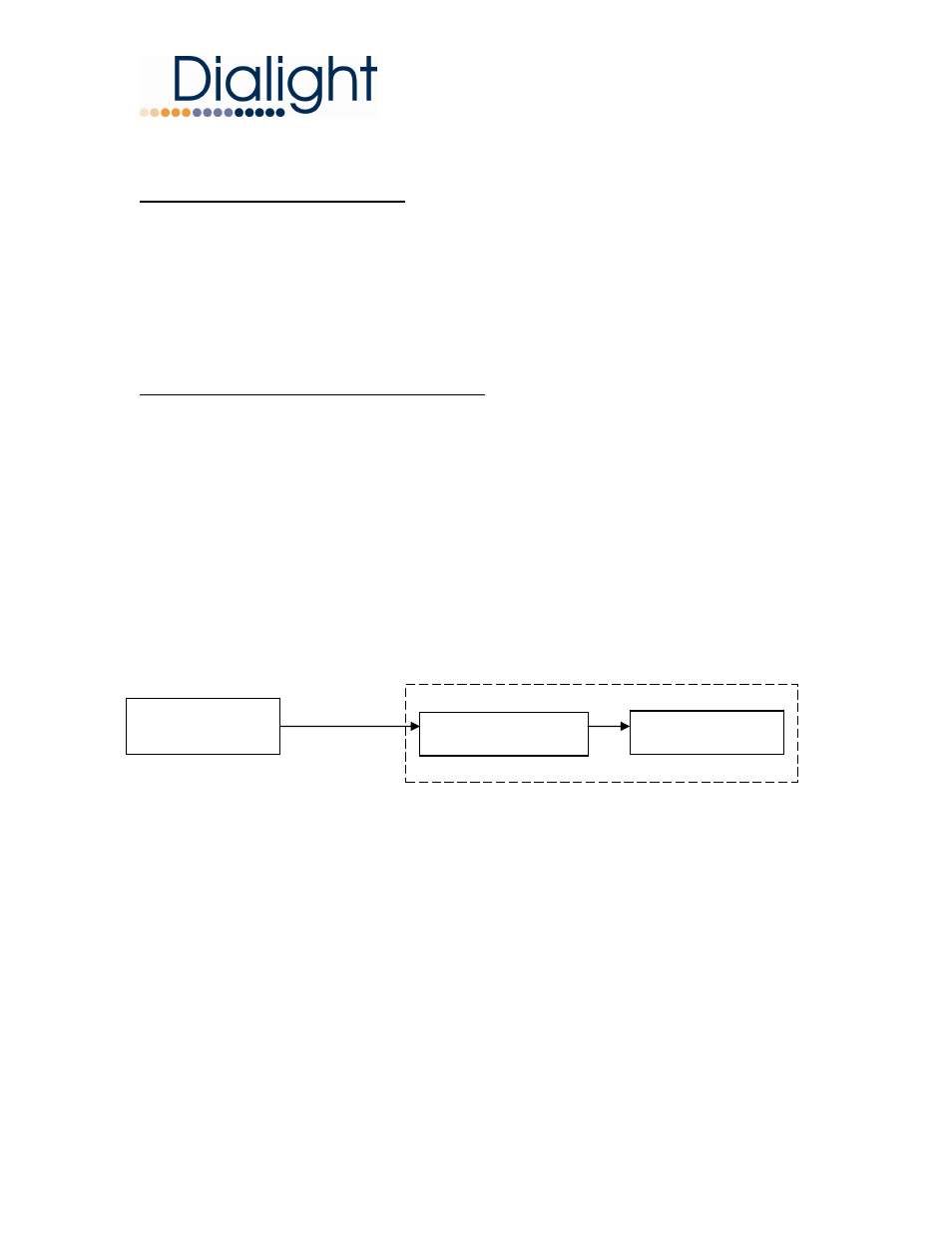
The block diagram in Figure 4 shows the major components of a typical Beacon
installation. The parts of the system are the LED Beacon and Controller. The
LED Beacon is made up of one LED module, which lights when current passes
through it. The LED Beacon contains its own internal power supply. The Beacon
is designed for use with an external controller. This external controller provides
the properly timed flashing signal, fault monitoring and alarm interfaces.
Beacon Assembly
Figure 3 - System Block Diagram
External
Controller
Power Supply
LED Module