Metric installation specifications, Chart 4 – DE-STA-CO Ferguson Rite-Torq Torque Limiters (Overload Clutches) Type RT, RTM, RTL, RTL-FCB User Manual
Page 11
11
METRIC INSTALLATION SPECIFICATIONS
Trip Torque
(Nm)
Max.
Actuator
Plate
Sprocket Mounting
Max.
Model
MIN.
MAX
RPM
Travel
Thread*
B.C.
NO.
Pilot Dia.
Bore
5
11,3
56,5
1800
1,85 mm
N/A
95,3 mm
4
63,5 mm
31,8 mm
20
58,4
113,0
1200
2,34 mm
N/A
123,8 mm
6
85,7 mm
44,5 mm
60
175,2
875,9
900
2,79 mm
N/A
152,4 mm
6
101,6 mm
57,2 mm
120
350,4
1751,8
600
3,71 mm
N/A
177,8 mm
6
120,7 mm
69,9 mm
CHART 4
NOTE: RTL & RTL FCB Torque Limiters are built in English dimensions unless otherwise noted. Metric
measures above are approximate conversion from English only.
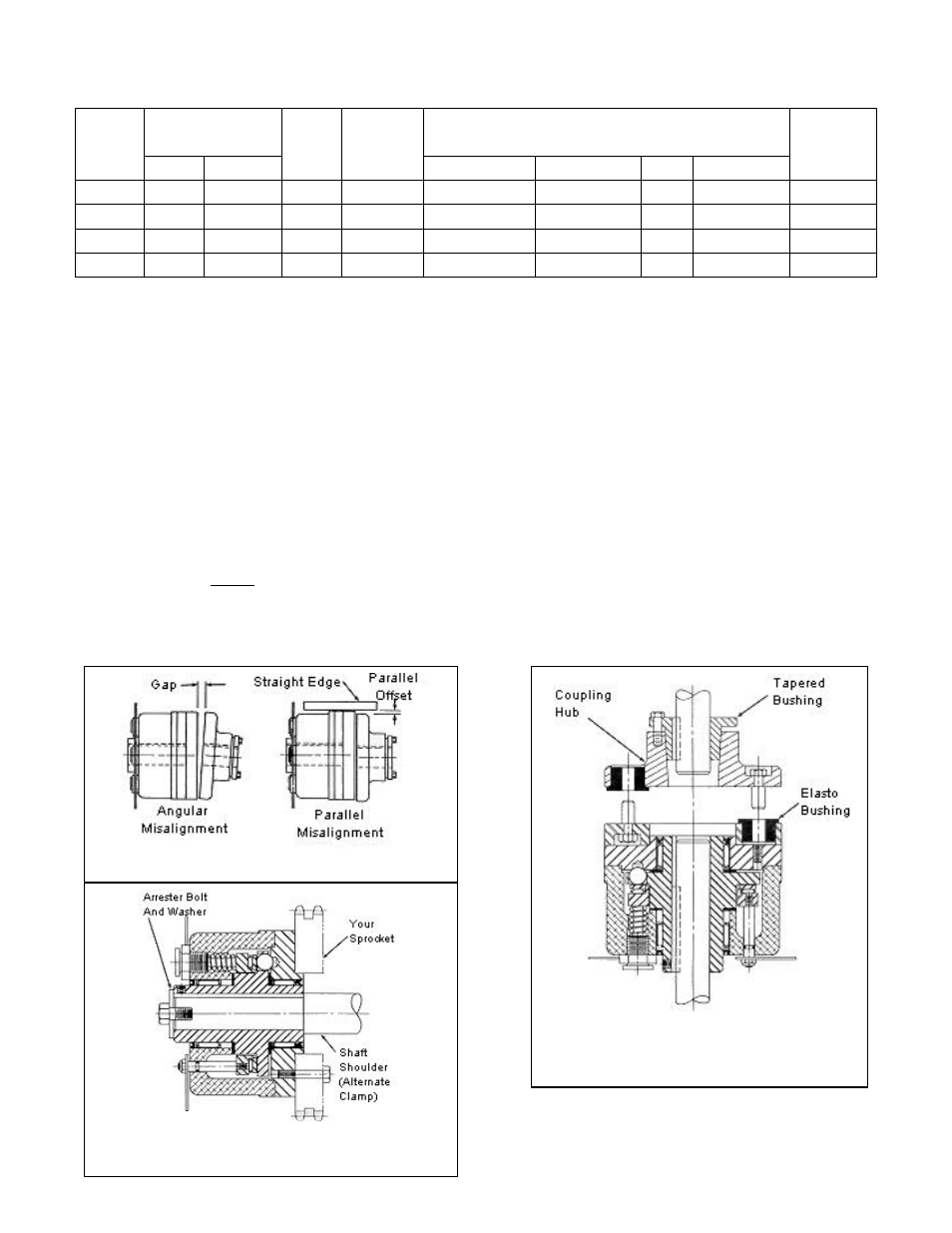
10. Slide torque limiter onto shaft of reducer, etc. with sprocket side as close as possible to the
bearing of the unit without rubbing. Secure torque limiter in place by tightening the two set
screws provided. Again, the use of Loctite® is recommended. Additional clamping can be
provided by using an arrestor bolt and washer to hold the unit against a shaft shoulder or
clamping collar (see Figure 5).
NOTE: Steps 11-12 apply to both RTL and RTL-FCB clutches.
11. Mount and adjust limit switch into proper position with switch trip plate.
12. Turn on power and inspect.
FIGURE 3 FIGURE 4
FIGURE 5
FIGURE 6