Rtl & rtl-fcb series, Imperial installation specifications, Chart 3 – DE-STA-CO Ferguson Rite-Torq Torque Limiters (Overload Clutches) Type RT, RTM, RTL, RTL-FCB User Manual
Page 10
10
RTL & RTL-FCB Series
NOTE: Steps 1-8 apply to RTL-FCB type clutch.
1. RTL-FCB (shaft/shaft) torque limiters are furnished with a flexible coupling to tolerate
moderate angular and/or parallel misalignment. The maximum acceptable angular
misalignment is 0.5 degree and maximum acceptable parallel offset is 0.005”.
2. Determine angular alignment by checking the gap between the coupling and the torque
limiter with a ruler, caliper or gauge. The gap should be even all around but not exceed 0.5
degree, as previously mentioned (see Figure 3).
3. Determine parallel alignment by use of a straight edge or indicator. A straight edge should
lie evenly on both members but not to exceed .005” (see Figure 4).
4. Fit key into shaft keyways and hand apply thin coat of anti-seize compound.
5. NOTE: Torque limiter and coupling with maximum bores have shallow keyways.
6. Separate torque limiter & coupling hub by pulling or prying apart (FCB Series only).
7. Mount the torque limiter to the driving or driven shaft on the slow speed side of the reducer
and secure it by tightening the two set screws. The use of Loctite
242 or similar adhesive
on the set screws is recommended.
8. Slide the coupling hub onto the shaft to be connected. Align the studs on the torque limiter
and hub with the holes in the elastomer bushings (Figure 6) in the opposing members and
slide the hub towards the torque limiter until the members are seated together. Align the
shafts per the above tolerances and tighten the coupling hub to the shaft using the furnished
standard QD type bushing.
NOTE: Steps 9-10 apply to basic RTL-type clutch.
9. Assemble the sprocket, pulley, etc. to the torque limiter using the tapped holes provided by
Industrial Motion Control.
CAUTION: SCREW THREAD DEPTH MUST NOT EXCEED THAT LISTED IN CHART 3.
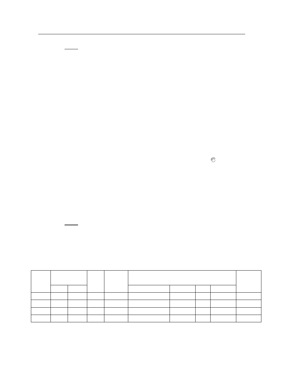
IMPERIAL INSTALLATION SPECIFICATIONS
Trip Torque
(IN-LBS)
Max.
Actuator
Plate
Sprocket Mounting
Max.
Model
MIN.
MAX
RPM
Travel
Thread*
B.C.
NO.
Pilot Dia.
Bore
5
100
500
1800
.073 IN.
¼-20X5/8 dp.
3.750 IN.
4
2.500
1.250 IN.
20
400
2000
1200
.092 IN.
¼-20X3/4 dp.
4.875 IN.
6
3.375
1.750 IN.
60
1200
6000
900
.110 IN.
5/16-18X3/4 dp.
6.000 IN.
6
4.000
2.250 IN.
120
2400
12000
600
.146 IN.
3/8-16X1 dp.
7.000 IN.
6
4.750
2.750 IN.
CHART 3