DE-STA-CO 722 INTERMITTOR User Manual
Page 7
5
SECTION 2: Overview
The sketches contained in this document are for illustrative purposes only. They are intended to
represent standard components and may not be shown to scale. The various models may be different
than shown, depending upon options chosen or the particular configuration of a unit.
2.1.
Intermittor Location Map
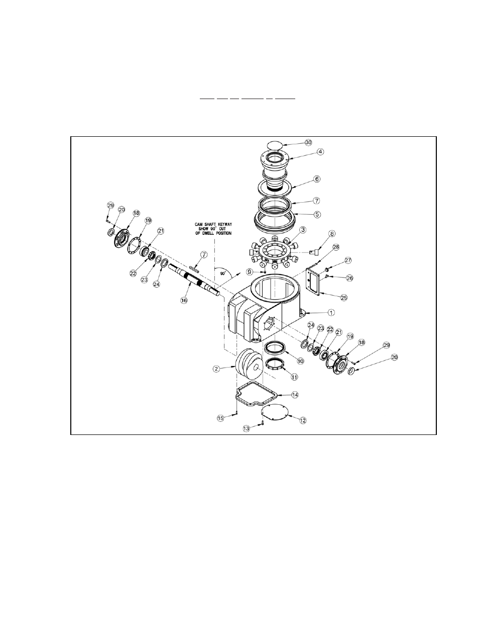
FIGURE 1
Intermittor Parts List
1.
Housing
2.
Cam
3.
Roller Gear Hub
4.
Roller Gear (Output) Shaft
5.
Bearing Ring &
Spacer Shims
6.
Oil Seal
7.
Timken Bearing
8.
Cam Followers
9.
Locking Set Screw
10. Bottom Timken Bearing
11. Locknut & Washer
12. Bottom Cover for
Output Shaft
13. Cap Screws
14. Bottom Housing Cover
15. Cap Screws
16. Cam (Input) Shaft
17. Drive Key (Cam)
18. Eccentric Bushing
19. Shim Pack
20. Oil Seal
21. Timken Bearing
22. Locknut
23. Lockwasher
24. Cam Spacer – not required
for all drive codes
25. Front Access Cover
26. Air Vent
27. Pipe Plug
28. Cap Screws
29. Cap Screws
30. Top Cover