Carlon – Carlon Rectangular Floor Box, Activation Kit, and Covers User Manual
Page 3
Yoke Mounted to Carlon Nonmetallic Covers
5. Position Yoke on underside of Cover.
6. Fasten Yoke to Cover using four #6 x
1
/
2
" flat head screws provided in Activation Kit.
Yoke Mounted to Carlon Brass Covers
5. Position Yoke on underside of Cover and retain in place using two #8x1-1/ 8" pan head screws provided with Cover.
6. Insert #8 x 1
1
/
8
" pan head screws into angled holes at the ends of cover and tighten into Floor Box ends.
1. Attach conductors to a standard electrical device (Duplex, GFCI or Single Round receptacle).
Canadian Applications: Per Canadian electric code, a separate bonding connection is required in nonmetallic
electrical boxes. Utilize Grounding Lug (Fig. 11) and green Ground Screw provided with Yoke.
2. Install electrical device in Yoke with device furnished 6-32 screws.
3. Attach the appropriate device plate using #6-32 x
5
/
8
" oval head screw(s) provided in Activation Kit.
Carlon
®
Nonmetallic Covers Installation
E9761__*, E9762__* & E9763__*
*B=Brown; C=Caramel; S=Slate
Plate Installation Power Applications
Plate Installation Low Voltage (Voice, Data & Video) Applications
3
1. A 6 port Low Voltage Plate (Fig. 12) is included in Activation Kit E976AK2. The Low Voltage Plate will accept
the following Manufacturer’s “Keystone” style jacks:
- Allen Tel - Amp - Dynacom - Homaco - Hubbell - Krone - Leviton - 3M - Ortronics - Wiremold -
Hellermann Tyton
2. Following Manufacturer’s instructions connect wire or cable to the jack(s). Snap wired jack(s) into Low Voltage
Plate with jack(s) aligned in the “UP” position. Snap blank modules into unused ports.
3. Attach the Low Voltage Plate to the yoke using #6-32 x
3
/
4
" oval head screws provided with Low Voltage Plate.
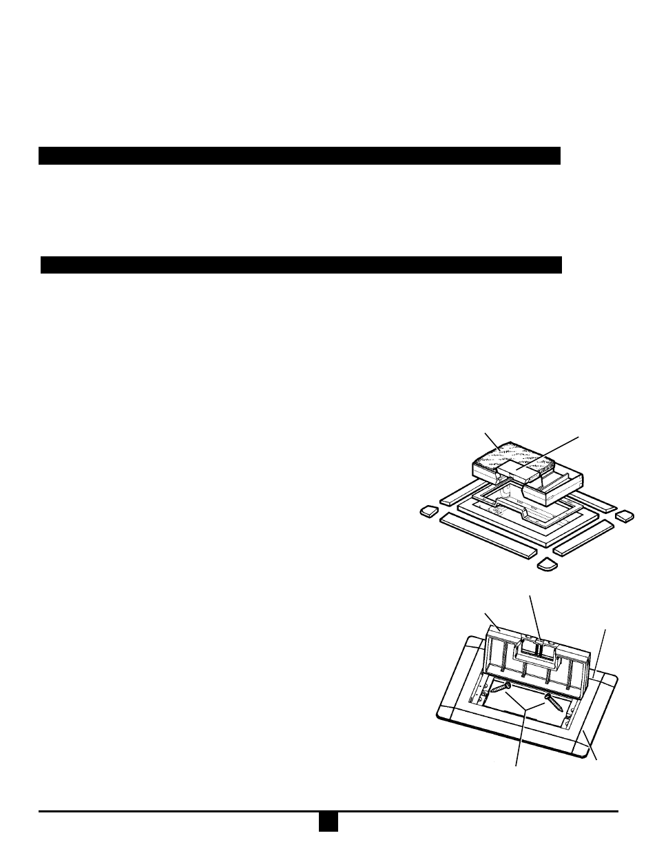
Fig. 14
Floor
Covering
#8 X 1
1
/
8
''
Cover mtg. screws
Cord door
Cord door
Fig. 15
Carpet
Flange
Cover
Score line
NOTE: Carlon Activation Kit E976AK2 is required for installation.
Nonmetallic carpet flanges will conceal opening sizes as follows: Single Gang
7
3
/
8
" x 5
1
/
8
", Two Gang 7
3
/
8
" x 8
1
/
2
" and Three Gang 7
3
/
8
" x 11
3
/
4
".
1. Determine type and thickness of floor covering to be used. Covers may be
installed in carpet, tile or other floor covering.
NOTE: Remember to check height of finished floor covering.
2. Mark a line a
1
/
8
" below desired final installed height of nonmetallic Cover’s
top surface. Using a saw, cut off box at marked height. (Refer to page 2,
Trim Out After Concrete Pour)
3. Methods of Installation
a. Tile or Carpet: The cover may either be installed as is with carpet flange or,
b. Tile: Carpet flange may be removed using a sawsall, jig saw or saber saw to cut along
the score lines. Avoid using pliers or similar tools to break away the flange. (Fig. 14)
If option of removing carpet flange is selected, set Cover so top surface of flange
is at finished tile height. Work tile to Cover flange.
c. Carpet: Install carpet up to Floor Box outside edge.
d. Tile or Carpet: Cover may be inverted and a section of carpet or tile installed in
the Cover to make the Cover less noticeable. Use template on page 4, Fig. 17, to
size section of floor covering to be installed in inverted cover. If inverted cover
option is chosen, small Cord Door must be removed and re-installed on the
opposite side of the cover. (Fig. 14)
4. Yoke provided in Activation Kit may be either mounted directly to bottom of the
Nonmetallic Cover or recessed down in the box. See Activation Kit Installation page 2.
5. To attach Cover to Floor Box, insert #8 x 1
1
/
8
" pan head screws (provided with Cover)
into angled holes at the ends of Cover and tighten into Floor Box ends. (Fig. 15)
Gross Automation (877) 268-3700 · www.carlonsales.com · [email protected]