Carlon, Activation kit e976ak2 installation – Carlon Rectangular Floor Box, Activation Kit, and Covers User Manual
Page 2
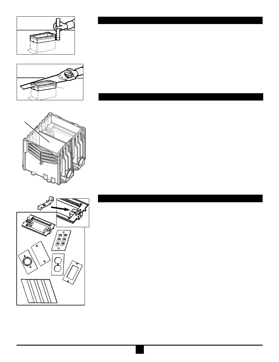
Trim Out After Concrete Pour
Single Gang Yoke Installation
Two and Three Gang Divider and Yoke Installation
1. Remove plastic cap.
2. Determine floor box height and mark cut off line. (Fig. 8)
a. For Carlon Nonmetallic Cover Installation go to page 3., steps 1, 2 and 3.
b. For Carlon Brass Cover Installation go to page 4, steps 1, 2 and 3.
3. Using handsaw, cut off box at marked height. (Fig. 9)
NOTE: Carlon Device Mounting Yoke may be either recessed down in the floor box,
or installed directly to bottom of the Carlon Covers.
Carlon
®
Activation Kit E976AK2 Installation
Divider
Activation Kit:
• Yoke/Activation ring
• Divider
• Insert plates
• Screws
Yoke
Divider
Fig. 13
Plates
Ground lug
Fig. 11
Low
voltage
plate
Fig. 12
Fig. 10
2
Box cut
off height
Fig. 8
Fig. 9
Yoke Recessed in Floor Box
1. Align Yoke in Floor Box slots (Fig. 7) and move yoke to desired level.
2. Insert #8 x
3
/
4
" pan head screws provided in Activation Kit into angled holes at
the ends of Yoke and tighten into Floor Box ends.
Yoke Mounted directly to Carlon Nonmetallic Covers
1. Position Yoke on underside of Cover.
2. Fasten Yoke to Cover using four #6 x
1
/
2
" flat head screws provided in
Activation Kit.
Yoke Mounted directly to Carlon Brass Covers
1. Position Yoke on underside of Cover and retain in place using two #8 x 1
1
/
8
"
pan head screws provided with Cover.
2. Insert #8 x 1
1
/
8
" pan head screws into angled holes at the ends of cover and
tighten into Floor Box ends.
IMPORTANT! It is necessary in accordance with NEC regulations to keep low
voltage (voice, data or video) separate from power requirements. To comply,
Divider provided in Activation Kit must be used.
Divider
1. If using two or three gang box for either all power or all communication, Divider
(Fig.13) is not required. Go to Step 5 per your application.
2. Break off the edge of the Yoke (score line) on the side that the Divider is to be
located. (Fig.10)
3. Cut Divider to length.
a. For Carlon Nonmetallic Cover, cut Divider
3
/
4
" below carpet flange underside at
installed position.
b. For Carlon Brass Cover, cut Divider
1
/
4
" below carpet flange underside at
installed position.
4. Slide divider down into slots created when 2 or 3 Carlon E976RFB Floor Boxes
are ganged together. (Fig. 10)
Yoke Recessed in Floor Box
5. Align Yoke in Floor Box slots (Fig. 5) and move yoke to desired level.
6. Insert #8 x
3
/
4
" pan head screws provided in Activation Kit into angled holes at
the ends of Yoke and tighten into Floor Box ends.
Gross Automation (877) 268-3700 · www.carlonsales.com · [email protected]