Bracket information, Figure 6 figure 7 figure 5 figure 8 – Bray 6P P_P Series User Manual
Page 9
Bray Series 6P
Operation and Maintenance Manual
9
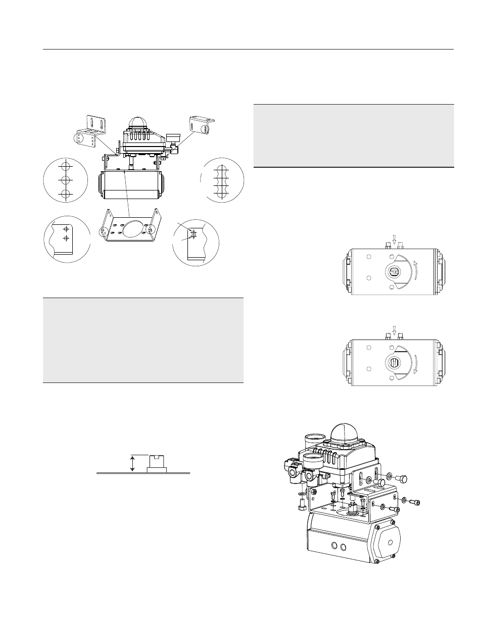
Bracket Information
The Series 6P is supplied with a standard adjustable
bracket for NAMUR mounting.
NOTICE
Care must be taken when assembling the two top
brackets to the bottom brackets. Please refer to
Figure 5 for proper placement. Failure to do so will
cause the positioner to be misaligned to the actuator
shaft causing binding and poor performance.
1. Standard actuator stem height (H) is .79”
(20mm), 1.18” (30mm), or 1.96” (50mm).
After checking “H” (Figure 6), assemble with
the bracket as shown in Figure 5.
2. Set rotation position of the actuator stem at the
zero point. For a Spring Return Actuator, Zero
point is the position at which the actuator rests
with no supply pressure. If a Double Acting
actuator is used, check actuator stem’s rotation
direction (clockwise or counter-clockwise) by
supplying pressure.
3. Attach the Series 6P to the bracket as shown in
Figure 8. This sets the alignment of the main
shaft and the center of the actuator stem.
NOTICE
Misalignment of the main shaft and the actuator stem
lowers the Series 6P’s sensitivity, because too much
side force will be imposed on the feedback shaft.
4. Tighten the Series 6P base and the bracket
hex-headed bolts to the actuator after checking
the position using the supplied Hex Head Bolts,
Spring Washers, and Lock Washers. M5 or
#10-32 bracket to actuator mounting screws are
supplied depend-
ing on specified
actuator drilling
H: 20, 30
H: 50
50
20
30
H: 20, 30
NAMUR TYPE 50
H: 50
NAMUR TYPE 30
NAMUR TYPE 20
H
Counter-Clockwise
Clockwise
Figure 6
Figure 7
Figure 5
Figure 8