Flow patterns – Bray MPF150_130_230_240 Series User Manual
Page 8
Installation and Maintenance Manual
MPF150/300, MPT230/240 Ball Valves
Date: April 2012 / Page 8 of 8
®
A Subsidiary of BRAY INTERNATIONAL, Inc.
FLOW-TEK, Inc.
Tel: 832.912.2300
© 2011 Flow-Tek, Inc.
8323 N. Eldridge Pkwy #100
Fax: 832.912.2301
Houston, Texas 77041
www.flow-tek.com
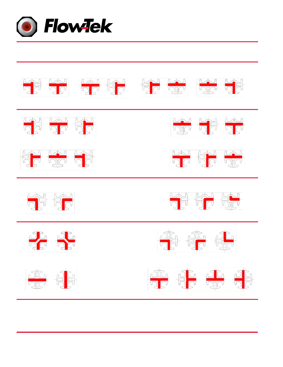
Flow Patterns
Position 1
Position 1
Position 1
Position 1
Position 1
Position 1
Position 1
Position 1
Position 1
Position 1
Position 1
Position 1
Position 1
Position 1
Position 2
Position 2
Position 2
Position 2
Position 2
Position 2
Position 2
Position 2
Position 3
Position 3
Position 4
Position 2
Position 2
Position 2
Position 3
Position 3
Position 3
Position 3
Position 3
Position 2
Position 2
Position 2
FLOWPLAN E
FLOWPLAN D
(standard)
FLOWPLAN I
FLOWPLAN A
(standard)
FLOWPLAN M
(standard)
- 4 Way LL Port 90° Turn
FLOWPLAN O
- 4 Way 90° Turn
FLOWPLAN B
FLOWPLAN N
- 4 Way L Port 180° Turn
FLOWPLAN P
- 4 Way 270° Turn
FLOWPLAN H
FLOWPLAN K
FLOWPLAN J
L-PORT: 180°
L-PORT: 90°
FLOWPLAN F
FLOWPLAN G
T-Port: 90°
T-Port: 180°
Optional Plans
Available
Consult Factory
4-WAY VALVES
Directional
Control and Shut
Off Combined in
One Valve
Valve Design Flexibility
Flow-Tek’s unique valve design offers excellent flexability, allowing easy in field rearrangement of all flow plans without
disassembly. In many cases it can be accomplished as easy as travel stop orientation or repositioning of the valve ball.
Please contact factory for detailed additional information on this valuable design feature.