Measurement range from 1m ω to 10mω – B&K Precision 886 - Manual User Manual
Page 37
34
measurement range from 1m
Ω to 10MΩ.
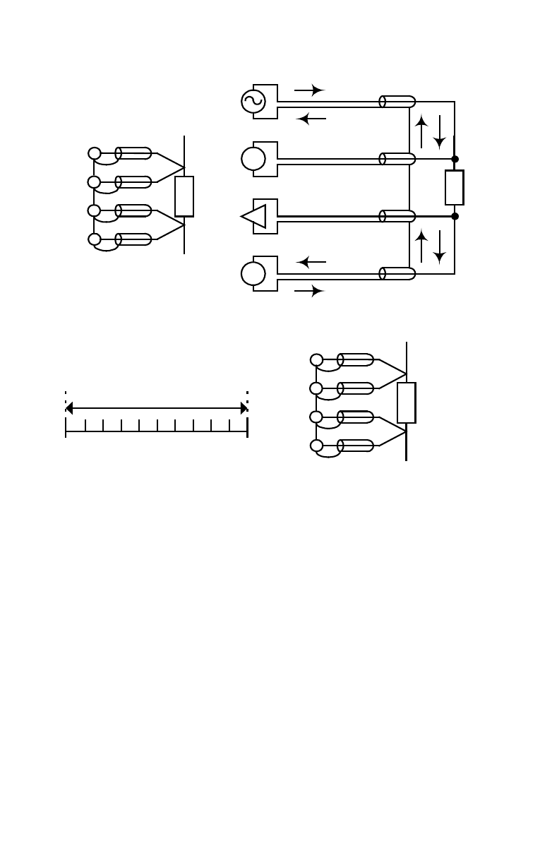
(b) BLOCK DIAGRAM
(a) CONNECTION
DUT
V
A
(c) TYPICAL IMPEDANCE
MEASUREMENT RANGE(£[)
4T
1m 10m 100m 1
10
1K 10K 100K 1M
100
10M
H
POT
DUT
H
CUR
L
CUR
L
POT
H
POT
DUT
H
CUR
L
CUR
L
POT
(d) 4T CONNECTION WITH SHILDING
Figure 3.5
Eliminating the Effect of the Parasitic Capacitor
When measuring the high impedance component (i.e. low
capacitor), the parasitic capacitor becomes an important issue
(Figure 3.6). In figure 3.6(a), the parasitic capacitor Cd is
paralleled to DUT as well as the Ci and Ch. To correct this
problem, add a guard plane (Figure 3.6(b)) in between H and L
terminals to break the Cd. If the guard plane is connected to
instrument guard, the effect of Ci and Ch will be removed.
This manual is related to the following products: