B&K Precision 889B - Manual User Manual
Page 28
27
H
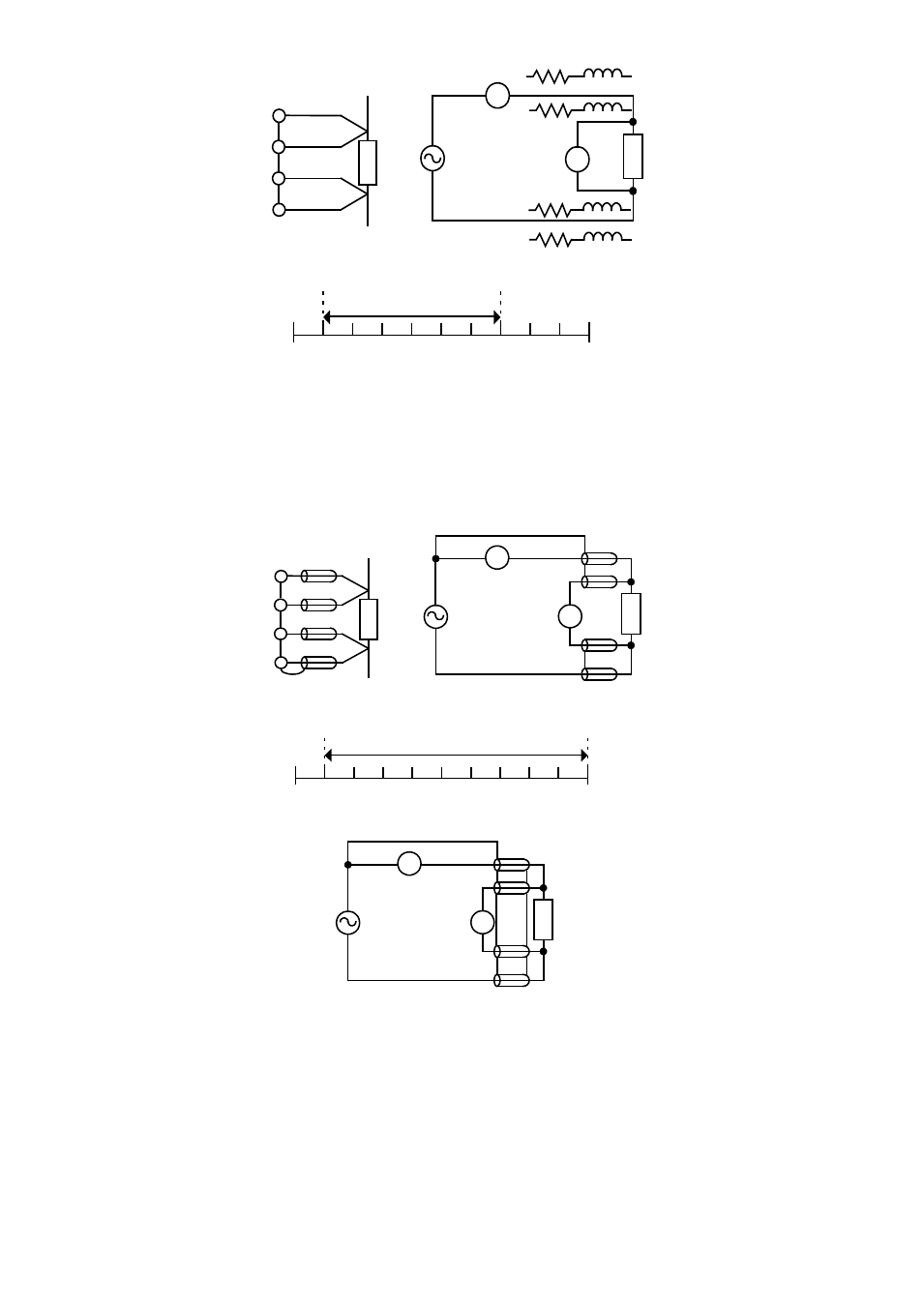
CUR
H
POT
DUT
(b) BLOCK DIAGRAM
DUT
V
A
(a) CONNECTION
(c) TYPICAL IMPEDANCE MEASUREMENT RANGE (£[)
4T
1m 10m 100m 1
10
1K 10K 100K 1M
100
10M
L
POT
L
CUR
Figure 4.3
5-Terminal (5T)
5-Terminal connection is the combination of 3T and 4T (Figure 4.4). It has four coaxial cables. Due to the
advantage of the 3T and 4T, this connection can widely increase the measurement range for 10m
Ω to 10MΩ.
(d) WRONG 4T CONNECTION
H
POT
DUT
(b) BLOCK DIAGRAM
(a) CONNECTION
(c) TYPICAL IMPEDANCE MEASUREMENT RANGE (£[)
5T
1m 10m 100m 1
10
1K 10K 100K 1M
100
10M
H
CUR
DUT
V
A
DUT
V
A
L
POT
L
CUR
Figure 4.4
4-Terminal Path (4TP)
4-Terminal Path connection solves the problem that caused by the test lead inductance. 4TP uses four coaxial
cables to isolate the current path and the voltage sense cable (Figure 4.5). The return current will flow through
the coaxial cable as well as the shield. Therefore, the magnetic flux that generated by internal conductor will
cancel out the magnetic flux generated by external conductor (shield). The 4TP connection increases the
measurement range from 1m
Ω to 10MΩ.