Application, 1 test leads connection, Eads – B&K Precision 889B - Manual User Manual
Page 27: Onnection, 26 4. application, And l, Figure 4.1
26
4. Application
4.1 Test Leads Connection
Auto balancing bridge has four terminals (H
CUR
, H
POT
, L
CUR
and L
POT
) to connect to the device under test (DUT).
It is important to understand what connection method will affect the measurement accuracy.
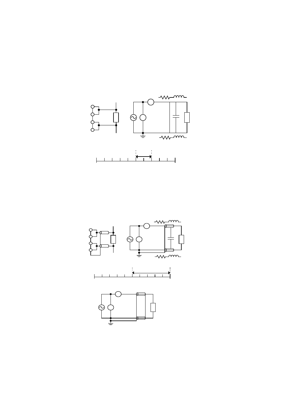
2-Terminal (2T)
2-Terminal is the easiest way to connect the DUT, but it contents many errors that are the inductance and
resistance as well as the parasitic capacitance of the test leads (Figure 4.1). Due to these errors in
measurement, the effective impedance measurement range will be limited at 100
Ω to 10KΩ.
R
H
CUR
H
POT
DUT
(b) BLOCK DIAGRAM
DUT
V
A
Co
o
L
o
R
o
L
o
(a) CONNECTION
(c) TYPICAL IMPEDANCE MEASUREMENT RANGE(£[)
2T
1m 10m 100m 1
10
1K 10K 100K 1M
100
10M
L
POT
L
CUR
Figure 4.1
3-Terminal (3T)
3-Terminal uses coaxial cable to reduce the effect of the parasitic capacitor (Figure 4.2). The shield of the
coaxial cable should connect to guard of the instrument to increase the measurement range up to 10M
Ω.
DUT
V
A
(d) 2T CONNECTION WITH SHILDING
H
CUR
H
POT
DUT
(b) BLOCK DIAGRAM
DUT
V
A
Co
R
o
L
o
R
o
L
o
Co doesn't
effect
measurement
result
(a) CONNECTION
(c) TYPICAL IMPEDANCE MEASUREMENT RANGE(£[)
3T
1m 10m 100m 1
10
1K 10K 100K 1M
100
10M
L
POT
L
CUR
Figure 4.2
4-Terminal (4T)
4-Terminal connection reduces the effect of the test lead resistance (Figure 4.3). This connection can improve
the measurement range down to 10m
Ω. However, the effect of the test lead inductance can’t be eliminated.