Asd series : product specifications – Atec Sorensen_ASD Series User Manual
Page 2
www.ProgrammablePower.com
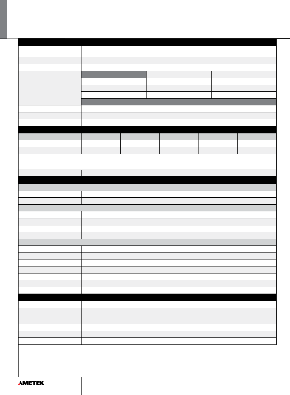
Output
Voltage Output
10kW
20kW
30kW
Noise (pk-pk)***
Noise (RMS)***
40Vdc
250A
500A
750A
150mV
40mV
60Vdc
167A
334A
501A
150mV
40mV
(*) Measured at the load terminals, with 1uF in parallel and 6ft of low-inductance load cable with supply operating at full load and nominal input line voltage.
(**) RMS noise is measured directly across the output terminal with supply operating at full load and nominal input line voltage.
(***) Value is for 30kW, single voltage models. Other variations may increase value by 2x.
Sense
To compensate load cables voltage drop, units can generate 2% additional voltage at full scale of output voltage.
ASD Series : Product Specifications
Input
Type: 3-phase, 3-wire plus ground, neutral not required. Not phase rotation sensitive
Voltage Ranges
342VAC to 440VAC (model D). Nominal rating is 380/400VAC.
432VAC to 528VAC (model E). Nominal rating is 480VAC
Frequency
Rated 47 through 63 Hz
Efficiency
>91% (typical), nominal line, full load.
Max Current, per phase, low line
400/380Vac
480Vac
10kW unit (1 module)
21Arms
17Arms
20kW unit (2 modules)
42Arms
33Arms
30kW unit (3 modules)
63Arms
50Arms
Current Inrush
200A Typical
Power Factor
>0.9 @ Full Load and at nominal line
Brownout Provisions
Designed to meet SEMI F47-0706, S3, S8, S14 at nominal input voltages
Output
Load Regulation (Specified at No load to Full load change, nominal AC input)
Voltage
0.1% of maximum output voltage/ current
Current
0.1% of maximum output voltage/ current
Line Regulation (Specified at ±10% of nominal AC input, constant load)
Voltage
0.05% of maximum output voltage/ current
Current
0.05% of maximum output voltage/ current
Transient Response
A 50% step load will recover to within 0.75% of original value within 1mSec
Stability
±0.05% of set point after 8 hrs. at fixed line, load and temperature. After 30min warm-up.
Analog Remote Programming
Voltage Accuracy
0.5% of full scale
Current Accuracy
1% of full scale
Power Accuracy
1.5% of full scale
Voltage Monitoring
0.5% of full scale
Current Monitoring
1% of full scale
Power Monitoring
1.5% of full scale
Programming range
0-10Vdc, 4-20mA
Output
Output Float
Units maybe put in series with the float limit of output terminals must be within ±150V of chassis potential
Parallel
Multiple units can be paralleled to form higher power systems. Chassis control loops are tied together so that resulting higher
power systems have the same transient response as a 30kW system. Control commands are only required to be sent to “master”
supply. Parallel supplies require a shielded CAT 5 cable (STP) and appropriate output wiring connections by the user.
Calibration
End user calibration is supported. All standard and digital calibration can be performed without removing covers.
Digital Control (Optional)
Ethernet (Modbus-TCP or Ethernet/IP), RS-485 (MODBUS-RTU)
Analog Control
All control signals are isolated from the outputs
2