I/q modulation, Ber measurement, Diversity simulation – Atec Rohde-Schwarz-SFQ Series User Manual
Page 13
TV Test Transmitter R&S
®
SFQ
13
I/Q modulation
In the I/Q modulator, the orthogonal I and Q
components of the RF signal are controlled
in amplitude and phase by the analog I and
Q signals from the coder. The two RF com-
ponents are added to give an output signal
that can be amplitude- and phase-modu-
lated as required. Assignment of I and Q
components can be interchanged in the
R&S SFQ so that an inverted RF signal is
obtained. High demands are placed on the
I/Q modulator particularly with a view to
high-order quadrature amplitude modula-
tion. The internal calibration of the R&S
SFQ ensures that I and Q paths have identi-
cal gain, the phase is exactly 90°
and carrier
suppression at least 50 dB. Non-ideal
behaviour of an I/Q modulator can be simu-
lated by detuning amplitude, phase and
carrier leakage in the R&S SFQ. As a result,
bit errors are produced that allow quality
assessment of receivers and demodulators.
BER measurement
The internal BER measurement facility
permits the BER of receivers to be mea-
sured without external equipment being
required. The demodulated data streams
are fed back to the R&S SFQ.
A selection can be made between the
serial inputs DATA, CLOCK (BNC connec-
tors, TTL level, 75
Ω) and the parallel input
for MPEG signals (sub-D, LVDS level). The
BER measurement is independent in its
function from other settings in the R&S
SFQ and can be used with all digital mod-
ulation modes. The current BER is perma-
nently displayed for this purpose.
A PRBS of 223-1 or 215-1 to ITU-T Rec.
O.151 can be selected and evaluated. It
ensures receiver synchronization and
allows measurements over a very wide
BER range.
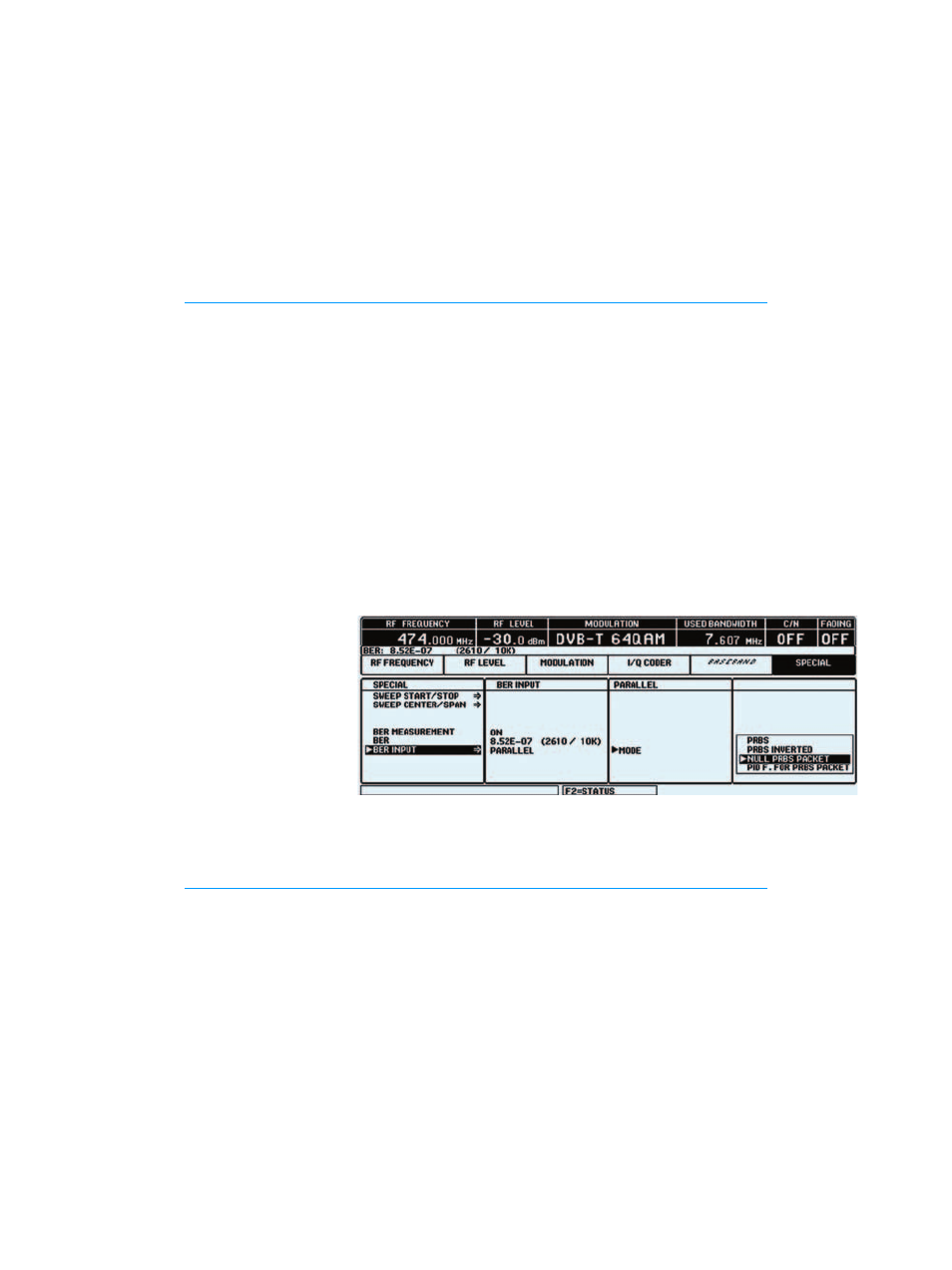
A serial BER measurement can be per-
formed after the demapper, for instance.
For parallel measurements on MPEG2
transmission systems, the R&S SFQ is set
to NULL PRBS PACKET. The BER measure-
ment can thus be carried out before the
Reed-Solomon decoder, for instance. The
BER setting menu
BER of set-top boxes can be determined
with the aid of an adapter board for the
Common Interface R&S SFQ-Z17.
The BER measurement facility is located
on the INPUT INTERFACE (model >02) or
on the DVB-T coder module, which means
that the R&S SFQ must be equipped with
at least one of these modules.
Diversity simulation
For testing diversity receivers, each
antenna of the receiver requires a sepa-
rate RF signal. The RF signals must carry
the same MPEG signal and be coupled to
each other via the reference frequency.
The interference simulation (noise, fad-
ing) produced by the individual transmit-
ters must not be intercorrelated; this can
be realized only by providing one R&S SFQ
per antenna. Only one MPEG2 transport
stream is used; the RF is coupled to the
reference frequency (see block diagram
opposite). To enable cascading, which is
required for this application, the noise
generator incorporates a splitter which
can be activated by means of the acces-
sory Cable Set R&S SFQ-Z5.