Atec Gigatronics-8650A Series User Manual
Page 12
8650A Series Universal Power Meter Specifications
10
Depending on sensor used.
11
MAP (Modulated Average Power),
PAP (Pulse Average Power), BAP (Burst Average Power).
12
Specified
performance applies with maximum averaging and 24 hour warm-up
at constant temperature.
13
Operates in Normal Mode only.
14
Display
contrast reduces above 50° C.
15
Does not apply to 80701A Sensor
below 500 MHz.
Specifications subject to change without notice.
Specifications describe the instrument’s warranted performance,
and apply when using the 80300A, 80400A, 80600A, and
80700A Series Sensors.
METER
Frequency Range: 10 MHz to 40 GHz
10
Power Range: -70 dBm to +47 dBm
(100 pW to 50 Watt)
10
Single Sensor Dynamic Range:
10
CW Power Sensors:
90 dB
Peak (Pulse) Power Sensors: 40 dB, Peak
50 dB, CW
Modulation Power Sensors: 87 dB, CW
80 dB, MAP/PAP
11
60 dB, BAP
11
Display Resolution: User selectable from
1 dB to 0.001 dB in Log mode, and from 1 to 4
digits of display resolution in Linear mode.
Meter Functions
Measurement Modes (Sensors):
CW (80300A, 80350A, 80400A, 80600A, and
80700A Series)
Peak (80350A Series)
MAP/PAP/BAP
11
(80400A, 80600A, and 80700A Series)
Averaging: User selectable, auto-averaging or
manual from 1-512 readings. Timed averaging from
20 ms to 20 seconds.
dB Rel and Offset: Power display can be
offset by -99.999 to +99.999 dB to account for
external loss/gain.
Configuration Storage Registers:
Allows up to 20 front panel setups.
Power Measurements and Display
Configurations: Any two of the following
channel configurations, simultaneously:
A, B, A/B, B/A, A-B, B-A, DLYA, DLYB
Number of Display Lines: 4
Sampling:
CW and Modulation Mode: 2.5 to 5 MHz asynchronous
Analog Bandwidth:
CW Mode:
≥
3 kHz
Modulation Mode: >10 MHz
Time Gating:
Trigger Delay: 0 to 327 ms
Gate Time: 10 µs to 327 ms
Holdoff Time: 0 to 327 ms
ACCURACY
50 MHz Calibrator: (Standard)
Calibrator: +20 dBm to -30 dBm
power sweep calibration signal to dynamically
linearize the power sensors.
Connector: Type N, 50
Ω
Frequency: 50 MHz, nominal
0.0 dBm Accuracy: ±1.2% worst case for
one year, over temperature range of 5º to 35ºC.
VSWR: <1.05 (Return Loss >33 dB) @ 0 dBm.
1 GHz Calibrator: (Option 12)
Required for 80700A Series Sensors.
Calibrator: +20 dBm to -30 dBm
power sweep calibration signal to dynamically
linearize power sensors.
Connector: Type N, 50
Ω
Frequency: (Switchable): 1 GHz, nominal;
50 MHz, nominal
0.0 dBm Accuracy: ±1.2% worst case for
one year, over temperature range of 5º to 35ºC.
VSWR: <1.07 (Return Loss >30 dB) @ 0 dBm.
800 MHz - 1 GHz Synthesizer
Specifications: (Option 12)
Power Range: +15 dBm to -30 dBm, settable in
1 dB steps.
Frequency: 800 MHz to 1 GHz, settable in
1 MHz steps.
Power Stability: <0.1 dB/Hour
Frequency Accuracy: ± 0.05%
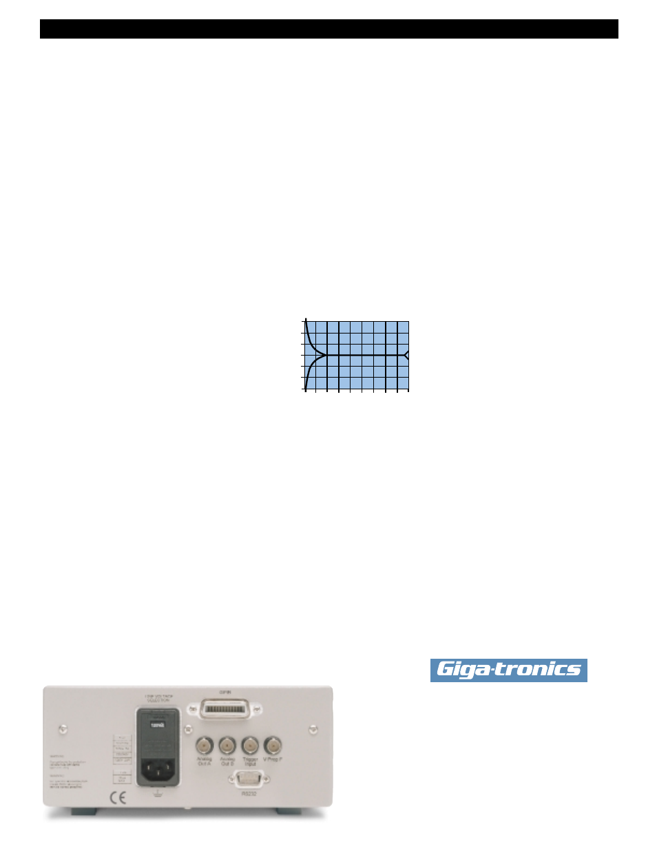
Instrumentation Linearity:
±0.02 dB over any 20 dB range from
-70 to +16 dBm.
15
±0.02 dB + (±0.05 dB/dB) from +16 to +20 dBm.
±0.04 dB from -70 to +16 dBm.
Graph shows linearity plus worst case zero set, and noise
versus input power
Temperature Coefficient of
Linearity: <0.3%/ºC temperature change following
Power Sweep calibration. 24 hour warm-up required.
Zeroing Accuracy: (CW)
Zero Set:
12
<±50 pW, <±100 pW with
80400A and 80600A Series Modulation Power Sensors.
<±200 pW with 80700A Series Sensors.
Zero Drift:
12
<
±100 pW during 1 hour,
<±200 pW with 80400A and 80600A Series Sensors,
<±400 pW with 80700A Series Sensors.
Noise: <±50 pW, <±100 pW with 80400A
and 80600A Series Modulation Power Sensors.
<±200 pW with 80700A Series Sensors.
Measurable over any 1 minute interval after zeroing,
3 standard deviations.
REMOTE INPUTS/OUTPUTS
V Prop F Input (BNC): Sets calibration factors
using source VpropF output.
13
Analog Output (2) (BNC): Provides an output
voltage of 0 to 10V for Channels 1 and 2 in
either Lin or Log units.
13
Does not operate in Swift
or Buffered modes.
Trigger Input (BNC): TTL trigger input signal
for Swift and Fast Buffered modes.
GPIB Interface: IEEE-488 and IEC-625 remote
programming
RS232 Interface: Programmable serial interface,
DB-9 connector
GENERAL SPECIFICATIONS
Temperature Range:
Operating: 0º to 55ºC (+32º to +131ºF)
14
Storage: -40ºC to 70ºC (-40º to +158ºF)
Power Requirements:
100/120/220/240V ±10%,
48 to 440 Hz, 25VA typical
Physical Characteristics:
Dimensions: 215 mm (8.4 in) wide,
89 mm (3.5 in) high, 368 mm (14.5 in) deep
Weight: 4.55 kg (10lbs)
ORDERING INFORMATION
POWER METERS
8651A
Single Input Universal Power Meter
(includes 1 sensor cable)
8652A
Dual Input Universal Power Meter
(includes 2 sensor cables)
ACCESSORIES
One manual, one power cord.
POWER METER OPTIONS
01 Rack mount kit
03 8651A Rear Panel Sensor and Calibrator Connections
04 8652A Rear Panel Sensor and Calibrator Connections
05 Soft Carry Case
07 Side Mounted Carrying Handle
08 Transit Case, (Includes Soft Carry Case)
09 Dual Rack Mount Kit (with assembly instructions)
10 Dual Rack Mount Kit (factory assembled)
12 1 GHz, 50 MHz Switchable Calibrator
13 8651A Rear Panel Input Connector
14 8652A Rear Panel Input Connectors
80301A
80310A
80320A
80321A
80322A
80325A
80330A
80401A, 80601A (CW)
80701A (CW)
-70
-64
-60
-50
-40
-40
-30
-67
-64
-60
-54
-50
-40
-30
-30
-20
-57
-54
-50
-44
-40
-30
-20
-20
-10
-47
-44
-40
-34
-30
-20
-10
-10
0
-37
-34
-30
-24
-20
-10
0
0
10
-27
-25
-20
-14
-10
0
10
10
20
-17
-16
-10
-4
0
10
20
20
-7
-7
0
6
10
20
30
30
3
3
10
16
20
30
40
40
13
13
20
25
30
40
44
50
20
20
3
2
1
0
-1
-2
-3
SENSORS
TYPICAL ERROR (dB)
Input, (dBm)
Giga-tronics Incorporated
4650 Norris Canyon Road
San Ramon, California 94583
Telephone: 800 726 4442 or
925 328 4650
Telefax: 925 328 4700
Web Site: www.gigatronics.com
© 1999 Giga-tronics Incorporated
GT-167-B