Epoch, Epoch 1000 i – Atec Panametrics-Olympus-Epoch-1000i User Manual
Page 15
15
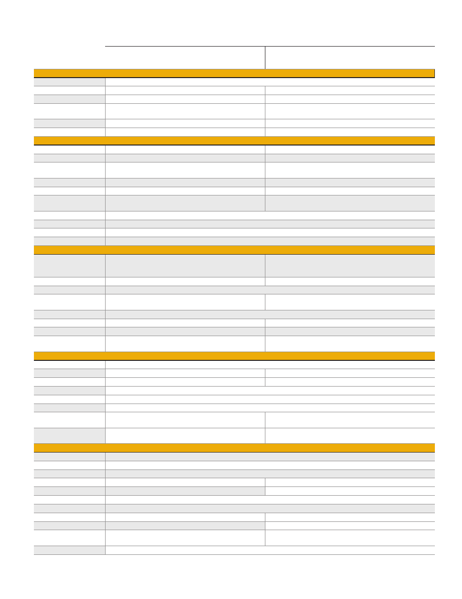
EPOCH 1000 Series Conventional/Phased Array Specifications*
EPOCH
®
1000, EPOCH 1000iR, EPOCH 1000i
(conventional UT mode)
EPOCH 1000i
(PA mode)
Pulser
Pulser Type
Tunable Square Wave
PRF
5 Hz to 6,000 Hz in 5 Hz increments
Manually adjustable. Maximum 1,520 Hz
Energy Settings
50 V to 475 V in 25 V increments
40 V or 80 V
Pulse Width
Adjustable from 25 ns to 5,000 ns (0.1 MHz) with Per‑
fectSquare
™
Technology
Adjustable from 40 ns to 1,000 ns with PerfectSquare
™
Technol‑
ogy
Damping
50 Ω, 100 Ω, 200 Ω, 400 Ω
Not applicable
Pulser Delay
Not applicable
0 to 10 µs, 2.5 ns resolution
Receiver
Gain
0 to 110 dB
0 to 80 dB
Maximum Input Signal
20 Vp‑p
250 mVp‑p per channel
Receiver Input Imped‑
ance
400 Ω ± 5%
50 Ω ± 10%
Receiver Bandwidth
0.2 MHz to 26.5 MHz @ –3 dB
0.5 MHz to 12.5 MHz @ –3 dB
Receiver Delay
NA
0 µs to 10 µs, 2.5 ns resolution
Digital Filter Settings
Standard filter set (EN12668‑1 Test & Compliant): 7 filters
Advanced filter set (not tested to EN12668‑1): 30 filters
6 filters
Rectification
Full wave, positive half wave, negative half wave, RF
Reject
0 to 80% FSH with visual warning
Amplitude Measurement
0% to 110% full‑screen height with 0.25% resolution
Measurement Rate
Equivalent to PRF in all modes
Calibration
Automated Calibration
• Velocity, Zero Offset
• Straight Beam (first back wall or echo-to-echo)
• Angle Beam (Soundpath or Depth)
• Velocity, Zero Offset, Sensitivity
• Soundpath or Depth (Zero Offset)
Test Modes
Pulse Echo, Dual, or Through Transmission
Pulse Echo
Units
Millimeters, inches, or microseconds
Range
3.60 mm to 26,808 mm (0.143 in. to 1055 in.)
Longitudinal velocity in steel
31 focal laws, 2.58 mm to 37.5 mm (0.101 in. to 14.76 in.)
Longitudinal velocity in steel
Velocity
635 to 15, 240 m/s (0.0250 to 0.6000 in./µs)
Zero Offset
0 µs to 750 µs
Not applicable
Display Delay
–59 mm to 25,400 mm (–2.323 in. to 1000 in.)
0 to max range
Refracted Angle
0° to 85° in 0.1° increments
61 angular focal laws, 0.5°, 1.0, 1.5°, or 2.0° increments
Adjustable from –80° to +80°
Gates
Measurement Gates
Two fully independent gates for amplitude and time‑of‑flight measurements
Measurement Mode
Soundpath
Soundpath, Depth
Interface Gate
Optional, with Gate 1 and Gate 2 tracking
Not applicable
Gate Start
Variable over entire displayed range
Gate Width
Variable from gate start to end of displayed range
Gate Height
Variable from 2% to 95% full‑screen height
Alarms
• Positive and negative threshold
• Minimum depth
• Positive and negative threshold (for selected focal law)
• Minimum depth (for selected focal law)
Reference Cursors
Two reference cursors for A‑scans
Two reference cursors for A‑scans; four reference cursors for im‑
ages
Measurements
Displayed Measurement
Six locations available (manual or auto selection)
Gate 1
Thickness, soundpath, projection, depth, amplitude, time‑of‑flight, min./max. depth, min./max. amplitude
Gate 2
Same as Gate 1
IF Gate (optional)
Thickness
Not applicable
Echo‑to‑Echo
Standard. Choose between Gate2‑1, Gate2‑IF, and Gate1‑IF
Standard
Other Measurements
Overshoot (dB) value for DGS/AVG, ERS (equivalent reflector size) for DGS/AVG, AWS D1.1/D1.5 rating (D), reject value
DAC/TVG
Standard
DAC Points
Up to 50 points, 110 dB dynamic range
Up to 20 points, 40 dB dynamic
Special DAC Modes
20% to 80% DAC, Custom DAC (up to 6 curves)
Not applicable
TVG Table
Up to 50 points, 110 dB dynamic range, compatible with IF
Gate at all PRF settings
Up to 20 points, 40 dB dynamic
Curved Surface Correction
Standard. Tube or bar OD correction for angle beam measurements