Specifications, Frequency – Atec Rohde-Schwarz-ESPI_Series_DatasheetsЙ User Manual
Page 12
12
Test Receiver ¸ESPI
Specifications
Specifications apply under the following conditions: 15 minutes warm-up time at ambient
temperature, specified environmental conditions met, calibration cycle adhered to and total
calibration performed. Data designated "nominal" applies to design parameters and is not
tested. Data designated "
= xx dB" indicates the standard deviation.
¸ESPI 3
¸ESPI 7
Frequency
Frequency range
9 kHz to 3 GHz
9 kHz to 7 GHz
Frequency resolution
0.01 Hz
Internal reference frequency
(nominal)
Aging per year
1)
1 × 10
6
Temperature drift (+5 °C to +45 °C)
1 × 10
6
With option ¸FSP-B4 (OCXO)
Aging per year
1)
1)
After 30 days of operation.
1 × 10
7
Temperature drift (+5 °C to +45 °C)
1 × 10
8
External reference frequency
10 MHz
Frequency display (receiver mode)
Display
numeric display
Resolution
0.1 Hz
Frequency display (analyzer mode)
Display
with marker or frequency counter
Resolution
span/500
Accuracy (sweep time
3 × auto sweep time)
±(frequency × reference error
+ 0.5 % × span + 10 % × resolution
bandwidth + ½ (last digit))
Frequency counter
Resolution
0.1 Hz to 10 kHz (selectable)
Count accuracy (S/N
25 dB)
±(frequency × reference error
+ ½ (last digit))
Display range for frequency axis
0 Hz,
10 Hz to 3 GHz
0 Hz,
10 Hz to 7 GHz
Resolution/accuracy of display range
0.1 %
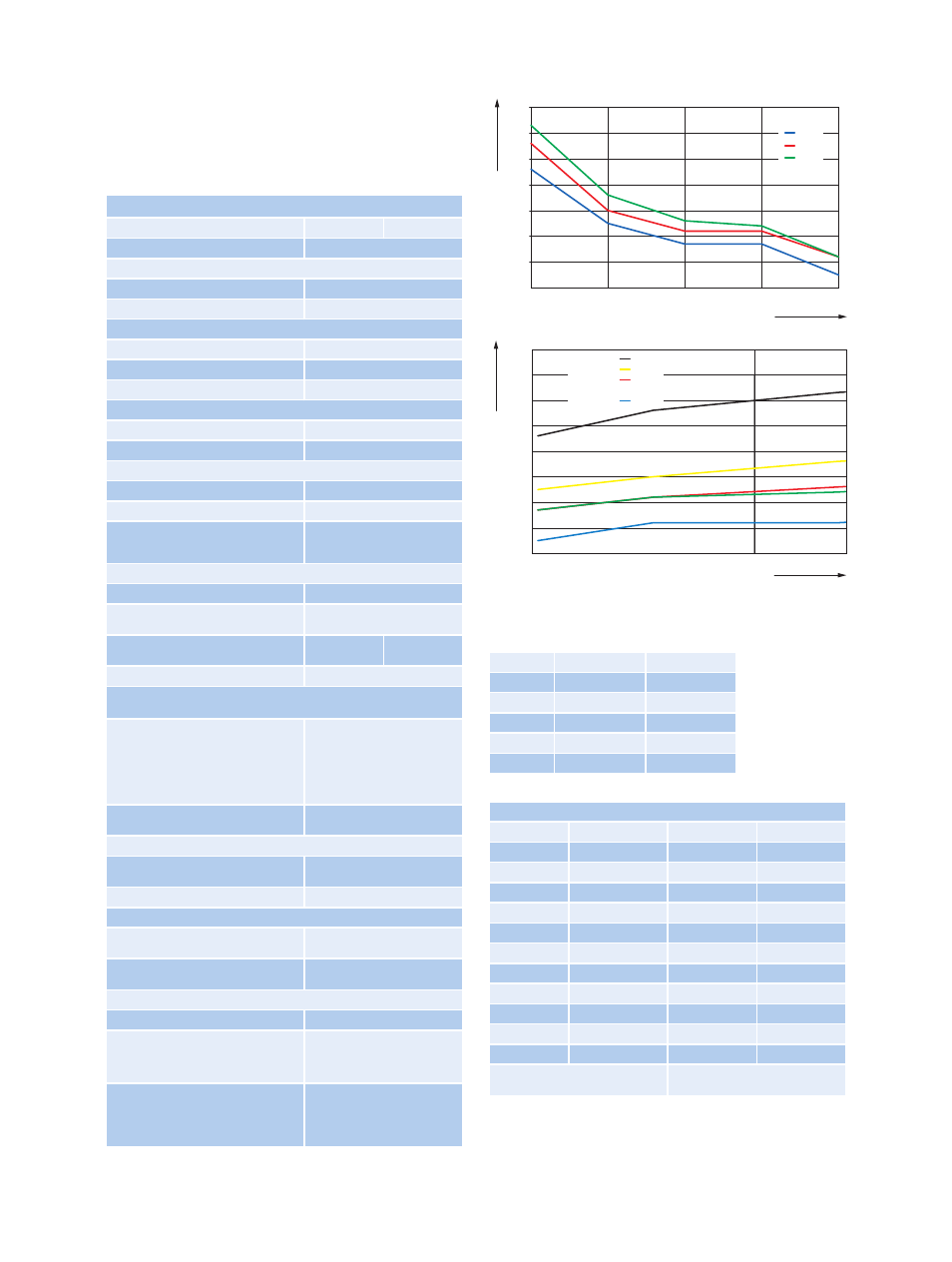
Spectral purity
(dBc (1 Hz))
SSB phase noise, f = 500 MHz, for frequencies
500 MHz see diagram
Carrier offset
100 Hz
1 kHz
10 kHz
100 kHz
2)
1 MHz
2)
10 MHz
2)
Valid for span
100 kHz.
84, typ. 90
typ.
100, 108
typ.
106, 113
typ.
110, 113
typ.
120, 125
typ.
145 typ.
Residual FM, f = 500 MHz, RBW 1 kHz,
sweep time 100 ms
typ. 3 Hz
Frequency scan (receiver mode)
Scan
scan with max. 10 subranges with
different settings
Measurement time per frequency
100 µs to 100 s, selectable
Sweep (analyzer mode)
Span 0 Hz (zero span)
Resolution
1 µs to 16 000 s
125 ns
Span
10 Hz
Max. deviation
2.5 ms to 16 000 s
1 %
IF bandwidths (receiver mode)
Bandwidths (–3 dB)
10 Hz to 10 MHz; in 1, 3, 10 sequence
Bandwidth error
100 kHz
300 kHz to 3 MHz
10 MHz
3 %
10 %
+10 %, –30 %
Shape factor BW
60 dB
: BW
3 dB
100 kHz
300 kHz to 3 MHz
10 MHz
5:1 (Gaussian filter)
15:1 (4-circuit synchronously
tuned filters)
7:1
Typical values for SSB phase noise (referenced to 1 Hz bandwidth)
Carrier offset
f
in
= 3 GHz
f
in
= 7 GHz
100 Hz
74 dBc
67 dBc
1 kHz
100 dBc
94 dBc
10 kHz
108 dBc
104 dBc
100 kHz
108 dBc
106 dBc
1 MHz
118 dBc
118 dBc
Preselector (option ¸ESPI-B2),
can be switched off in analyzer mode
Filter
Frequency range
Bandwidth (–6 dB)
1
<150 kHz
230 kHz
fixed
2
150 kHz to 2 MHz
2.6 MHz
fixed
3
2 MHz to 8 MHz
2 MHz
tracking
4
8 MHz to 30 MHz
6 MHz
tracking
5
30 MHz to 70 MHz
15 MHz
tracking
6
70 MHz to 150 MHz
30 MHz
tracking
7
150 MHz to 300 MHz
60 MHz
tracking
8
300 MHz to 600 MHz
80 MHz
tracking
9
600 MHz to 1000 MHz
100 MHz
tracking
10
1 GHz to 2 GHz
highpass filter
tracking
11
2 GHz to 3 GHz
highpass filter
fixed
Preamplifier (9 kHz to 3 GHz)
can be switched between preselector and
1st mixer, gain 20 dB
–130
–120
–110
–100
–90
–80
–70
–60
100 Hz
1 k
10 k
100
1 M
Offset frequency
SSB phase noise in dBc (1 Hz)
0.5
3
7
f
in
in GHz
–130
–120
–110
–100
–90
–80
–70
–60
–50
0
5
7
Frequency in GHz
SSB phase noise in dBc (1 Hz)
Offset
frequency
100 Hz
1 k
10 k
100 k
1 M