Atec Megger-ODEN-AT User Manual
Page 2
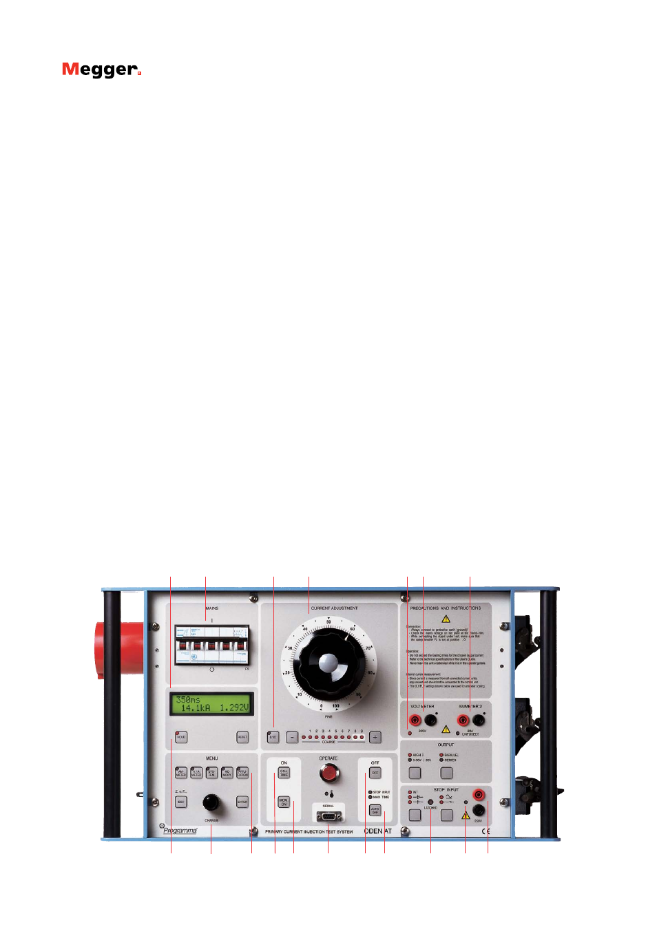
ODEN AT
Primary Current Injection Test System
1
2
4
5
7
12
11
10
9
8
3
6
13
14 15
16
17 18
Features and Benefits
1.
Display. The display presents time, output current, voltage,
current shown on ammeter 2 and phase angle. You can scroll
through entities Z, P, Q, R, X, S, power factor (cos φ) and I
max.
2.
Miniature circuit breaker used for current output. Inter-
rupts output current. Can also be actuated manually for safe
disconnection of load.
3.
Current reduction button. Used during setting to reduce the
output current to 1/30. Useful in order to avoid for example
unintentional tripping and overheating.
4.
Fine adjustment knob. Knob for fine adjustment of current
and +/- buttons for coarse adjustment.
5.
Indicator lamps. Indicate whether ammeter 2 or the voltme-
ter is enabled.
6.
Input for voltmeter. Used to measure voltage and for mi-
crohmmeter measurement.
7.
Input for ammeter 2. Used to measure current in an external
circuit (in a current transformer´s secondary winding for ex-
ample).
8.
Hold function. This function freezes readings on the display.
9.
Selection/setting (CHANGE) knob. Selects the desired
menu option (shown in the display window). Also used to
change numerical values.
10.
Setting buttons. Personnel unfamiliar with ODEN AT can
use the pre-defined settings very effectively, while experienced
users can make their own basic settings.
• Ammeter. Used to set the main current-output ammeter. You
can select the desired range or select autoranging.
• V/A Meter. Toggles between the voltmeter and ammeter 2.
Also used to select the desired range or select autoranging.
• System. Used for general settings.
• Memory. Used to save or recall settings to or from the ten
ODEN AT memories. One of these memories contains the de-
fault (pre-defined) settings that are invoked when ODEN AT is
powered up.
• Application. Used to invoke the desired measurement mode:
automatic recloser, sectionalizer or microhmmeter.
ODEN AT can also be set to generate pulse trains with user-se-
lectable pulse and pause times.
11.
Injection. Starts current injection and timing.
12.
Momentary Injection. When this button is used, injection
continues only as long as it is pressed. Useful in order to avoid
for example overheating.
13.
RS232 for computer. ODEN AT is equipped with a serial port
for communication with PC (for transfer of test data for ex-
ample).
14.
Manual shut-off. Injection and timing are stopped when this
button is pressed.
15.
Automatic injection stop. Generation stops after a user-spec-
ified interval or when condition at the input is met. The diodes
show the selected OFF condition.
16.
Stop-condition indicator. Indicates that a stop condition is
met, voltage or contact triggered.
17.
Status indicator. Indicates if a contact connected to the input
is closed or if voltage is present.
18.
Stop input. Used to freeze a reading or stop injection. Activat-
ed when current is interrupted by the object being tested, when
an external contact is actuated or when a voltage is applied or
removed.