Inputs – Atec Agilent-8566B User Manual
Page 12
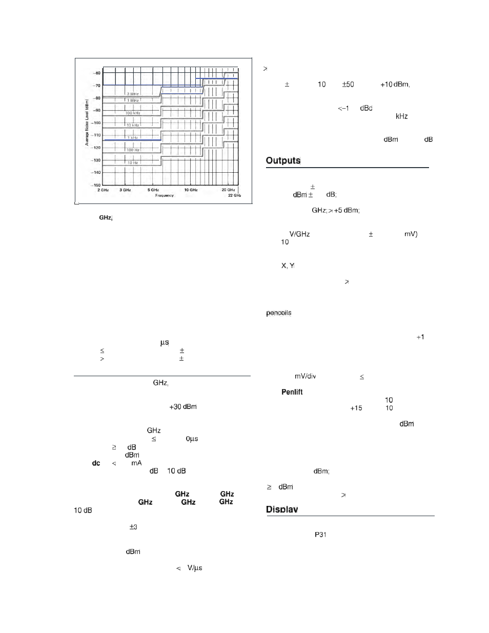
Fig. 6. Specified average displayed noise level,
2.0 to 22
preselected tuning range
Marker
(frequency and amplitude are read out continuously)
Marker Type
Frequency Accuracy
Normal
same as center frequency accuracy
Delta
same as frequency span accuracy
Amplitude Accuracy
Normal
same as reference level accuracy +
scale fidelity between the reference
level and marker position
Delta
same as frequency response
uncertainty and scale fidelity
between two markers
Sweep Time Accuracy (1
to 1500s full sweep)
200 second sweep time, 10%
200 second sweep time, 30%
Inputs
RF Input
100 Hz to 22
precision type-N
female connector, dc-coupled
Maximum Input Level
ac
Continuous power:
from 50 ohm source
Mixer protected by diode limiter,
100 Hz-2.5
Pulse power: 100 W, 1
pulse width with
50
input attenuation
(
I
0
peak power to input mixer)
100
damage level
Input Attenuator0
to 70
in
steps
SWR (typical)
Tune Frequency
Input
100Hzto
2
to
5.8
to
Attenuation
2.5
5.8
22
1.2
1.5
1.9
0 dB*
2.3
3.0
3.0
‘when tuned to within
MHz of signal
IF Input
Maximum Input Level
ac
+10
continuous power from
50
ohm source
dc
20 V with rise time of 1
External Sweep Trigger Input (rear panel) Must be
2.4 V (5 V max), 1 kohm nominal input impedance.
External Frequency Reference Input
Must equal
5 MHz 25 Hz or
MHz
Hz, 0 to
50 ohm nominal input impedance. Analyzer performance
will be degraded unless frequency reference phase noise
and spurious signals are
40
single sideband
(1 Hz) referred to 10 MHz at a 100 Hz to 10
offset.
Quasi-Peak (rear panel; nominal values)
Video Input
0 to 2 V, 139 ohm input impedance
21.4 MHz IF Input
Nominally -11
with 10
input attenuation, 50 ohm input impedance
Calibrator (front panel)
100 MHz (frequency reference error x 100 MHz)
-10
0.3
50 ohm impedance, nominal
1st LO (front panel)
2.3 to 6.1
50 ohm impedance, nominal
Sweep and Tune Output (rear panel)
-1
of tuned frequency (2% + 10
kohm impedance, nominal
Display Outputs (typical parameters)
X, Y, and Z outputs for auxiliary CRT displays.
1 V for full deflection
Z
0 to 1 V intensity modulation, -1 V blank
BLANK
TTL level 2.4 V for blanking
Compatible with most oscilloscopes.
Recorder Outputs (typical parameters)
Outputs to drive all current HP X-Y recorders using positive
or TTL pen uplift.
Horizontal Sweep Output (X-axis)
A voltage proportional to the horizontal sweep of the
frequency sweep generator. 0 V for left edge,
0
V for right edge; 1.7 kohm impedance, nominal.
Video Output (Y-axis)
Detected video output (before A-D conversion)
proportional to vertical deflection of the CRT trace
100
from 0 to 1 V; 475 ohm impedance,
nominal.
Output (Z-axis)
During sweep, pen down 0 V from
ohm source
During retrace, pen up
V from
kohm source
21.4 MHz Output (rear panel, typical)
21.4 MHz; 50 ohm impedance, nominal: -20
for a signal
at reference level. In log scales, the IF output logarithmically
related to RF input signal; in linear, the output is linearly
related.
Frequency Reference (rear panel, typical)
10.000 MHz, 0
50 ohm output impedance
10 MHz Output (rear panel, typical)
5
to ohm output impedance
Video Output 0 to 2 V, 10 ohm output impedance
Cathode Ray Tube
Post deflection accelerator,
aluminized
phosphor, electrostatic focus and
deflection.
Viewing Area
Approximately 9.6 cm vertically
by 11.9 cm horizontally (3.8 in x 4.7 in)