Supplemental characteristics, Programming resolution, Readback resolution – Atec Agilent-N3300A User Manual
Page 6: Programmable slew rate, Programmable short, Programmable open
6
Supplemental
Characteristics
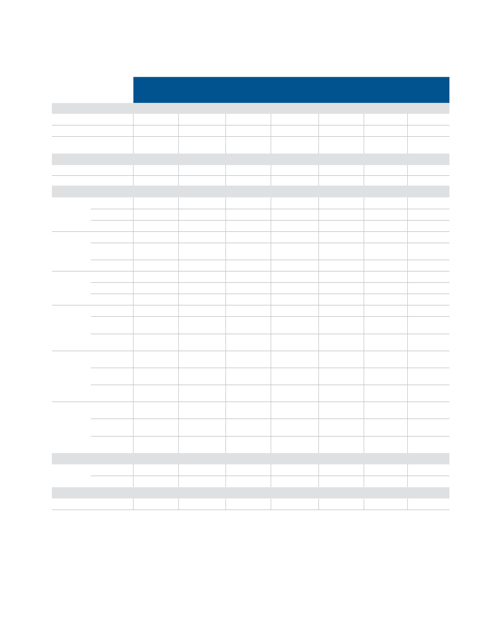
Table A-2 lists the supplemental characteristics, which are not warranted but are
descriptions of typical performance determined either by design or type testing.
Table A-2
N3302A
N3303A
N3304A
N3304A-J01
Special order
option
N3305A
N3306A
N3307A
Programming resolution
Constant current mode
0.05/0.5 mA
0.02/0.2 mA
0.1/1 mA
0.1/1 mA
0.1/1 mA
0.2/2 mA
0.05/0.5 mA
Constant voltage mode
0.1/1 mV
0.4/4 mV
0.1/1 mV
0.135/1.35 mV
0.25/2.5 mV
0.1/1 mV
0.25/2.5 mV
Constant resistance mode
0.07/0.7/7/
70 mΩ
0.82/8.2/
82 mΩ
0.035/0.35/
3.5/35 mΩ
0.05/0.5/5/
50 mΩ
0.085/0.85/
8.5/ 85 mΩ
0.0175/0.175/
1.75/17.5 mΩ
0.17/1.7/
17/170 mΩ
Readback resolution
Current
0.05/0.5 mA
0.02/0.2 mA
0.1/1 mA
0.1/1 mA
0.1/1 mA
0.2/2 mA
0.05/0.5 mA
Voltage
0.1/1 mV
0.4/4 mV
0.1/1 mV
0.135/1.35 mV
0.25/2.5 mV
0.1/1 mV
0.25/2.5 mV
Programmable slew rate
1
Current
ranges
Slow band
500–25 kA/s
167–8330 A/s
1 k–50 kA/s
1 k–50 kA/s
1 k–50 kA/s
2–100 kA/s
500–25 kA/s
Fast band ≥3 V 50 k–2.5 MA/s
16.7 k–833 kA/s
100 k–5 MA/s
100 k–5 MA/s
100 k–5 MA/s
200 k–10 MA/s
50 k–2.5 MA/s
Fast band <3 V 50 k–250 kA/s
16.7 k–83.3 kA/s 100 k–500 kA/s
100 k–500 kA/s
100 k–500 kA/s
200 k–1 MA/s
50 k–250 kA/s
Voltage
ranges
Slow band
1 k–50 kV/s
4 k–200 kV/s
1 k–50 kV/s
1.33 k–66.6 kV/s
2.5 k–125 kV/s
1 k–50 kV/s
2.5 k–125 kV/s
Fast band ≥3 V 100 k–
500 kV/s
400 k–
2 MV/s
100 k–
500 kV/s
133 k–
666 kV/s
250 k–
1.25 MV/s
100 k–
500 kV/s
250 k–
1.25 MV/s
Fast band <3 V 100 k–50 kV/s
400 k–200 kV/s
100 k–50 kV/s
133 k–66.6 kV/s
250 k–125 kV/s
100 k–50 kV/s
250 k–125 kV/s
Resistance
range 1
Slow band
44–1125 Ω/s
540–13.5 kΩ/s
22–560 Ω/s
30–745 Ω/s
55–1400 Ω/s
11–280 Ω/s
110–2800 Ω/s
Fast band ≥3 V 2250–34 kΩ/s
27 k–408 kΩ/s
1120–17 kΩ/s
1500–22.6 kΩ/s
2800–42.5 kΩ/s
560–8.5 kΩ/s
5600–85 kΩ/s
Fast band <3 V 2250–3.4 kΩ/s
27 k–40.8 kΩ/s
1120–1.7 kΩ/s
1500–2.26 kΩ/s
2800–4.25 kΩ/s
560–850 Ω/s
5600–8.5 kΩ/s
Resistance
range 2
Slow band
440–11.25 kΩ/s 5.4 k–135 kΩ/s
220–5600 Ω/s
300–7450 Ω/s
550–14 kΩ/s
110–2800 Ω/s
1.1 k–28 kΩ/s
Fast band ≥3 V 22.5 k–
340 kΩ/s
270 k–
4.08 MΩ/s
11.2 k–
170 kΩ/s
15 k–
226 kΩ/s
28 k–
425 kΩ/s
5600–
85 kΩ/s
56 k–850 kΩ/s
Fast band <3 V 22.5 k–
34 kΩ/s
270 k–
408 kΩ/s
11.2 k–
17 kΩ/s
15 k–
22.6 kΩ/s
28 k–
42.5 kΩ/s
5600–
8.5 kΩ/s
56 k–
85 kΩ/s
Resistance
range 3
Slow band
4.4 k–
112.5 kΩ/s
54 k–
1.35 MΩ/s
2.2 k–
56 kΩ/s
3 k–
74.5 kΩ/s
5.5 k–
140 kΩ/s
1.1 k–
28 kΩ/s
11 k–
280 kΩ/s
Fast band ≥3 V 225 k–
3.4 MΩ/s
2.7 M–
40.8 MΩ/s
112 k–
1.7 MΩ/s
150 k–
2.26 MΩ/s
280 k–
4.25 MΩ/s
56 k–
850 kΩ/s
560 k–
8.5 MΩ/s
Fast band <3 V 225 k–
340 kΩ/s
2.7 M–
4.08 MΩ/s
112 k–
170 kΩ/s
150 k–
226 kΩ/s
280 k–
425 kΩ/s
56 k–
85 kΩ/s
560 k–
850 kΩ/s
Resistance
range 4
Slow band
44 k–
1.125 MΩ/s
540 k–
13.5 MΩ/s
22 k–
560 kΩ/s
30 k–
745 kΩ/s
55 k–
1.4 MΩ/s
11 k–
280 kΩ/s
110 k–
2.8 MΩ/s
Fast band ≥3 V 2.2 M–
34 MΩ/s
27 M–
408 MΩ/s
1.12 M–
17 MΩ/s
1.5 M–
22.6 MΩ/s
2.8 M–
42.5 MΩ/s
560 k–
8.5 MΩ/s
5.6 M–
85 MΩ/s
Fast band <3 V 2.25 M–
3.4 MΩ/s
27 M–
40.8 MΩ/s
1.12 M–
1.7 MΩ/s
1.5 M–
2.26 MΩ/s
2.8 M–
4.25 MΩ/s
560 k–
850 kΩ/s
5.6 M–
8.5 MΩ/s
Programmable short
Maximum
66 mΩ
200 mΩ.
33 mΩ
33 mΩ
33 mΩ
17 mΩ
33 mΩ
Typical
40 mΩ
100 mΩ
20 mΩ
20 mΩ
25 mΩ
12 mΩ
20 mΩ
Programmable open
≥ 20 kΩ
≥ 80 kΩ
≥ 20 kΩ
≥ 20 kΩ
≥ 20 kΩ
≥ 20 kΩ
≥ 80 kΩ
1. Slew rate bands are the ranges of programmable slew rates available. When you program a slew rate value outside the indicated bands, the electronic
load will automatically adjust the slew rate to fit within the band that is closest to the programmed value. It is not necessary to specify the band, only the
slew rate itself.
Below 3 volts, the maximum bandwidth of the electronic load is reduced by a factor of ten to one. For example, in the current range for Model N3302A,
the maximum slew rate is specified as 2.5 MA/s, below 3 volts the maximum slew rate would be 250 kA/s. Any slew rate programmed between
2.5 MA/s and 250 kA/s would produce a slew rate of 250 k/s. Slew rates programmed slower than 250 kA/s would still correctly reflect their
programmed value. Note that if you are using transient mode to generate a high frequency pulse train, a reduced slew rate might cause the load to
never reach the upper programmed value before beginning the transition to the lower programmed value. So even though the transient mode is still
operational at lower voltages, a fast pulse train with large transitions may not be achievable.