Ets terrasas - specifications – Atec Elgar-ETS Series User Manual
Page 4
www.ProgrammablePower.com
Photovoltaic array modeling
Specifications
Model Number
1
ETS60X14C
ETS80X10.5C
ETS150X5.6C
ETS80X15C
ETS600X _ _
ETS1000 X10
Output voltage, Voc (V)
60
80
150
80
600
1000
Output current, Isc (A)
14
10.5
5.6
15
8.3, 16.7, 25
10
Output power @ 0.85FF (W)
714
714
714
1020
4250, 8500, 12750
8500
MPP tracking speed (Hz)
2
250
250
250
120
200
200
I-V curve resolution (# of pts)
1024
1024
1024
1024
1024
1024
Output capacitance
< 10nF
< 10nF
< 10nF
< 70uF
< 70uF
< 3uF
Output isolation (Vpk)
±1000
±1000
±1000
± 600
± 600
± 1400
Available I/O
Ethernet
Ethernet
Ethernet
Ethernet
Ethernet
Ethernet
Remote sense
2V
2V
2V
2V
10V
10V
AC Input Voltage, V
(max operational range)
85-264VAC
85-264VAC
85-264VAC
100-130VAC low
170-230VAC high
C: 187-242VAC
D: 342-440 VAC
E: 396-528 VAC
C: 187-242VAC
D: 342-440 VAC
E: 396-528 VAC
Input frequency, Hz
47-63
47-63
47-63
47-63
47-63
47-63
Power factor
> 0.99 typical
> 0.99 typical
> 0.99 typical
> 0.7 typical
> 0.9 typical
> 0.9 typical
Output voltage noise
Measured across a 1μF capacitor at
the end of a 1.8m(6ft) line at full
load, 20MHz
< 0.35 Vpp
< 0.35 Vpp
< 0.6 Vpp
< 1 Vpp
< 0.6 Vpp
< 0.6 Vpp
Output current noise
Measured with hall effect sensor,
BW = 650kHz
< 60 mApp
< 60 mApp
< 60 mApp
< 100 mApp
< 200 mApp
< 200 mApp
Operating temperature
0-40 degs C
0-40 degs C
0-40 degs C
0-50 degs C
0-50 degs C
0-50 degs C
Physical dimensions
22.6 x 1.7 x 19.0 in
574 x 43.6 x 483 mm
21 lbs (9.5 kg)
22.6 x 1.7 x 19.0 in
574 x 43.6 x 483 mm
21 lbs (9.5 kg)
22.6 x 1.7 x 19.0 in
574 x 43.6 x 483 mm
21 lbs (9.5 kg)
20.4 x 1.7 x 19.0 in
518 x 43.6 x 483 mm
23 lbs (10.5 kg)
25.5 x 5.3 x 19.0 in
64.7 x 13.3 x 48.3 cm
5kW 40 lbs (18 kg)
10kW 60lbs (27kg)
15kw 80lbs (36kg)
25.5 x 5.3 x 19.0 in
64.7 x 13.3 x 48.3 cm
10kW 60lbs (27kg)
Regulatory
Certified to UL/CSA 61010 and IEC/EN 61010-1
Notes
1 See next page for full listing of model numbers and configurations
2 Maximum MPPT rate of the inverter under test. Closed loop analog output bandwidth is much greater.
ETS TerraSAS - Specifications
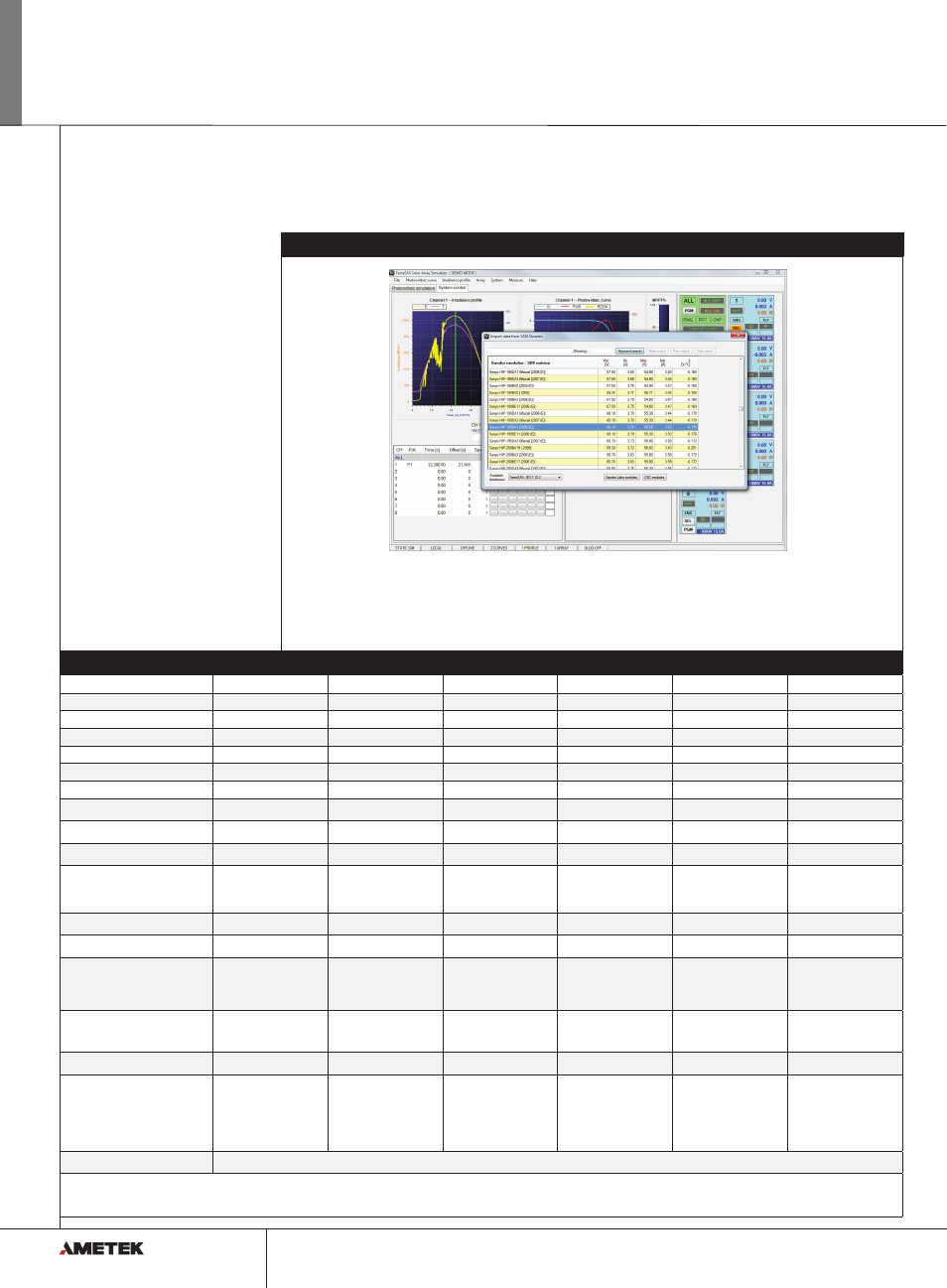
Photovoltaic array modeling
This feature allows the user to quickly define
an array of PV panels connected in series or
parallel. Using this array modeling capability, the
user can simulate such real world conditions as
mismatched panels, which result in multiple hump
I-V curves. It is important to verify that the MPPT
algorithm finds and settles on the universal MPP,
not a local maximum.
Import module data
from embedded
Sandia database and
create I-V Curve
Build the array model by
binding to the desired
curve and specifying the
array size
The effects of shadowing, aging and faulty modules
can be previewed in real time. the resulting I-V
curve can be dragged and dropped to any output
for inverter testing.
294