Amplitude modulation, Phase modulation – Atec Agilent-11792A User Manual
Page 3
3
150 kHz
≤
f
c
<10 MHz
Amplitude Modulation
RATES:
20 Hz to 10 kHz, 150 kHz
≤
f
c
<10 MHz.
20 Hz to 100 kHz, 10 MHz
≤
f
c
≤
1300 MHz.
DEPTH: to 99%.
ACCURACY
2, 3, 6
:
AM Accuracy
Frequency Range
Rates
Depths
±2% of reading
150 kHz – 10 MHz
50 Hz – 10 kHz
5% – 99%
±1 digit
±3% of reading
150 kHz – 10 MHz
20 Hz – 10 kHz
to 99%
±1 digit
±1% of reading
10 MHz – 1300 MHz
50 Hz – 50 kHz
5% – 99%
±1 digit
±3% of reading
10 MHz – 1300 MHz
20 Hz – 100 kHz
to 99%
±1 digit
±1.5% of reading 1300 MHz – 26.5 GHz
50 Hz – 50 kHz
5% – 99%
±1 digit
±3% of reading
10 MHz – 26.5 GHz
20 Hz – 100 kHz
to 99%
±1 digit
For rms detector add ±3% of reading.
FLATNESS
5, 7
:
Flatness
Frequency Range
Rates
Depths
±0.3% of reading
10 MHz – 1300 MHz
90 Hz – 10 kHz
20% – 80%
±1 digit
±0.3% of reading
10 MHz – 26.5 GHz
90 Hz – 10 kHz
20% – 80%
±1 digit
DEMODULATED OUTPUT DISTORTION:
<0.3% THD for
≤
50% depth.
<0.6% THD for
≤
95% depth.
For f
c
>1300 MHz add 0.4% THD.
FM REJECTION (50 Hz to 3 kHz BW)
3
:
FM Rejection
Frequency Range
Rates
Deviations
<0.2% AM
250 kHz – 10 MHz
400 Hz or 1 kHz
<5 kHz
peak
<0.2% AM
10 MHz – 1300 MHz
400 Hz or 1 kHz
<50 kHz
peak
<0.2% AM
10 MHz – 26.5 GHz
400 Hz or 1 kHz
<50 kHz
peak
RESIDUAL AM (50 Hz to 3 kHz BW): <0.01%
rms
.
Supplemental Characteristics:
DETECTORS: +peak, –peak, ±peak/2, peak hold, average (rms
sinewave calibrated), rms.
MAXIMUM DEPTH, RESOLUTION, AND MAXIMUM DEMODU-
LATED OUTPUT SENSITIVITY ACROSS AN OPEN CIRCUIT
(600
Ω
output impedance)
5
:
Maximum
Maximum Demodulated
Depths
Resolution
Output Sensitivity
0.1%
0.01V / percent
AM
peak
≥
40.0%
0.01%
0.1V / percent
AM
peak
<40.0%
0.001%
(rms detector only)
0.1V / percent
AM
rms
<3.0%
Phase Modulation
RATES:
200 Hz to 10 kHz, 150 kHz
≤
f
c
<10 MHz.
200 Hz to 20 kHz, 10 MHz
≤
f
c
≤
1300 MHz.
200 Hz to 20 kHz, 10 MHz
≤
f
c
≤
26.5 GHz.
ACCURACY
3
:
±4% of reading ±1 digit, 150 kHz
≤
f
c
<10 MHz.
±3% of reading ±1 digit, 10 MHz
≤
f
c
≤
1300 MHz.
±3% of reading ±1 digit, 10 MHz
≤
f
c
≤
26.5 GHz.
For rms detector add ±3% of reading.
DEMODULATED OUTPUT DISTORTION: <0.1% THD.
AM REJECTION (for 50% AM at 1 kHz rate)
3
:
<0.03 radians peak (50 Hz to 3 kHz BW).
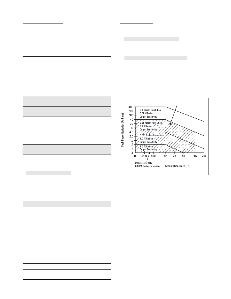
MAXIMUM DEVIATION, RESOLUTION, AND MAXIMUM
DEMODULATED OUTPUT SENSITIVITY ACROSS AN OPEN
CIRCUIT (600
Ω
output impedance)
5
:
Supplemental Characteristics:
MODULATION RATES: usable from 20 Hz to 100 kHz with degraded
performance.
DETECTORS: +peak, – peak, ±peak/2, peak hold, average (rms
sinewave calibrated), rms.
2. Not to exceed for stated accuracy: 50 Hz to 40 kHz rates with rms detector.
3. Peak residuals must be accounted for in peak readings.
5. For optimum flatness, cables should be terminated with their characteristic
impedance.
6. For peak measurements only: AM accuracy may be affected by distortion generat-
ed by the measuring receiver. In the worst case this distortion can decrease accu-
racy by 0.1% of reading for each 0.1% of distortion.
7. Flatness is the variation in indicated AM depth for constant depth on input signal.