Coil testing, Operator interface and operation, Flexible modular design – Atec Baker-DX Series User Manual
Page 2: Hardware and software
Coil testing
The Baker DX unit is among the first on the market to have specific
coil testing software. The Baker DX unit can be placed into an
impulse mode for quick application of voltage to the coils. The soft-
ware can store and display up to 200 waveforms on the screen for
quick analysis of coil condition. Utilize SKFs Error Area Ratio (EAR)
method to calculate the differences between the coils for quick, accu-
rate analysis of the data. The EAR calculation greatly reduces opera-
tor error and automatically indicates a defective coil when the result
is out of the programmed tolerance level. Report and analyze your
data easily with bar charts to help locate and report faulty coils, and
for an at-a-glance summary of all coils tested.
Operator interface and operation
The 12,7 × 17,0 cm (5.0 × 6.7 in.) touch and color display is an
industrial, ruggedized touch screen to handle the rough operation of
daily industrial use.
The operator interface has been developed with large icons for
easy touch operation, even with electrical gloves. The interface is
designed with a left-to-right flow to reduce the number of touches
and is intuitive and easy to operate. The software will automatically
prompt the operator to save the data if the save button is not
selected, reducing the possibility of lost data.
Flexible modular design
Hardware and software
The Baker DX can be built specifically to fit your needs. The unit can
be configured to only perform the surge and DC tests, or you can add
the resistance test. If you would like the ability to perform all avail-
able tests, add the Inductance, Impedance, Phase Angle and Capaci-
tance tests to take advantage of one of the most comprehensive
motor analyzers on the market. The Baker DX is available in a 4, 6 or
12 kV unit. The 6 and 12 kV units can also be configured in a high
output (HO) version to supply additional energy when surge testing
to properly test larger HP motors. If higher voltage is needed, any of
these units can act as a host for a Baker PP24, 30 or 40 kV power
pack. DC motors can also be tested with the Baker DX by utilizing the
AT101 ZTX or adding a span testing fixture.
Table 1
Tests and capabilities of the Baker DX unit.
Failure modes
Winding
resistance IR test
DA/PI
test
DC step
voltage
DC
HiPot
Surge
Inductance Capacitance
Impedance
Phase
angle
D/Q
Weak insulation turn-turn
X
Weak insulation phase-phase
X
Weak insulation coil-coil
X
Turn-turn shorts
X
X
X
X
X
X
Phase-phase shorts
X
X
X
X
X
X
Coils-coils shorts
X
X
X
X
X
X
Open coils
X
X
X
X
X
X
Reversed coils
X
X
X
X
X
Unbalanced phases
X
X
X
X
X
X
Weak ground wall insulation
X
X
X
X
Dirty windings
X
X
X
X
X
Moisture
X
X
X
X
X
Feeder cables
X
X
X
X
X
Motor lead line connections
X
RLC measurements screen.
Testing individual coils within the stator.
Coil testing screen.
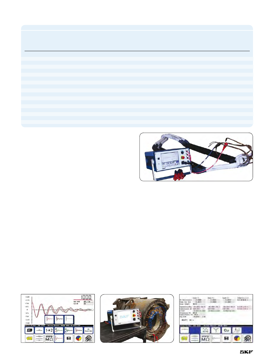
Testing a coil utilizing the Baker DX.
2