Atec Agilent-4286A User Manual
Page 17
17
Non-operation conditions
Temperature . . . . . . . . . . . . . . . . . . . . . . . . . . . . . . . . . . . . . . . . . . . . . . . . . . . . . . . . . . . 40°C to 65°C
Humidity
@wet bulb temperature . . . . . . . . . . . . . . . . . . . . . . . . . . . . . . . . . . . . . . . . . . . . . . . . . . . . . . . 15 % to 95 % RH
Altitude . . . . . . . . . . . . . . . . . . . . . . . . . . . . . . . . . . . . . . . . . . . . . . . . 0 to 15,240 meters (50,000 feet)
Others
EMC . . . . . . . . . . . . . . . . . . . . . . Complies with CISPR 11 (1990) / EN 55011 (1991) : Group 1, Class A
Complies with IEC 801-2 (1991) / EN 50082-1 (1992) : 4 kV CD, 8 kV AD
Complies with IEC 801-3 (1984) / EN 50082-1 (1992) : 3 V/m
Complies with IEC 801-4 (1988) / EN 50082-1 (1992) : 1 kV Power lines / 0.5 kV Signallines
Note: When tested at 3 V/m according to IEC 801-3/1984, the measurement accuracy will be within specifications
over the full immunity test frequency range of 26 to 1000 MHz except when the analyzer frequency is identical
to the transmitted interference signal test frequency.
Safety . . . . . . . . . . . . . . . . . . . . . . . . . . Complies with EN61010-1:1993 + A2 / IEC61010-1:1990 + A1, A2
Pollution Degree 1
Certifies with CSA C22.2 N0.231-M89
Power requirements . . . . . . . . . . . . . . . . . . . . . . . 90V to 132V, or 198V to 264V, 47 to 66 Hz, 500VA max
Weight
Mainframe . . . . . . . . . . . . . . . . . . . . . . . . . . . . . . . . . . . . . . . . . . . . . . . . . . . . . . . . . . . . . . . . . . . . . . . . . . . . 28 kg
Test head . . . . . . . . . . . . . . . . . . . . . . . . . . . . . . . . . . . . . . . . . . . . . . . . . . . . . . . . . . . . . . . . . . . . . . . . . . . . 0.3 kg
Dimensions
Mainframe . . . . . . . . . . . . . . . . . . . . . . . . . . . . . . . . . . . . . . . . . . . . . . . . . . . 426 (W)
×
234 (H)
×
537 (D) mm
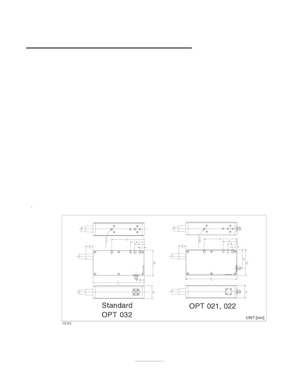
Test Head . . . . . . . . . . . . . . . . . . . . . . . . . . . . . . . . . . . . . . . . . . . . . . . . . . . . . . . . See Figure 12 and Figure 13.
Figure 12. Dimensions of Test Heads (1/2)