Atec Agilent-34461A User Manual
Page 9
9
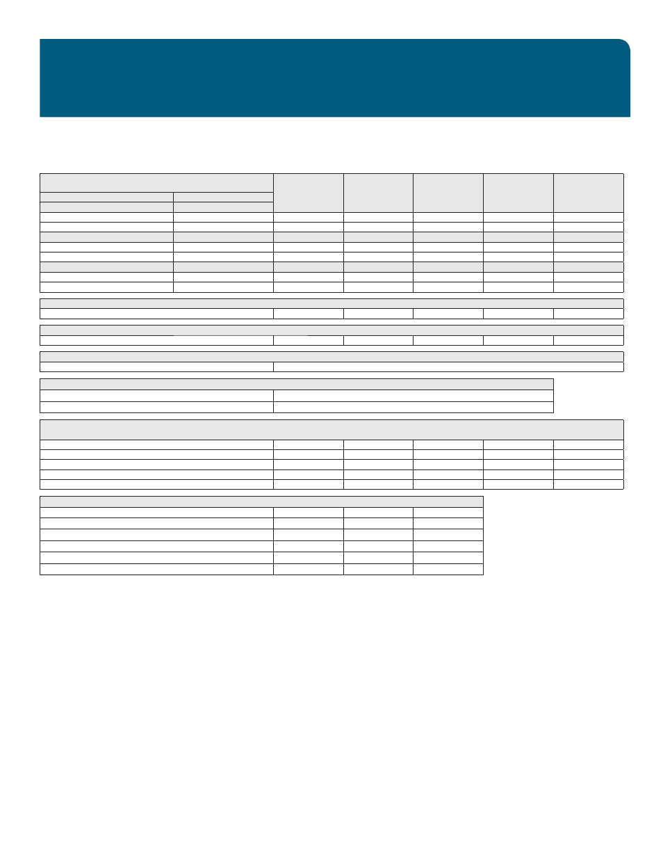
34460A
S P E C I F I C A T I O N S
1. For DC: Specifi cations are for 60-minute warm-up, aperture of 10 or 100 NPLC,
and auto zero on.
For AC: Specifi cations are for 60-minute warm-up, slow AC fi lter, sine wave.
2. 20% overrange on all ranges, except 1000 DCV, 750 ACV, 3 A AC, and diode test.
3. Relative to calibration standards.
4. Add this for each °C outside T
CAL
± 5 °C.
5. Specifi cations are for sine wave input > 0.3% of range and > 1 mVrms.
750 ACV range limited to 8 x 10
7
Volt–Hz.
6. Low-frequency performance: three fi lter settings are available: 3 Hz, 20 Hz, 200 Hz.
Frequencies greater than these fi lter settings are specifi ed with no additional errors.
7. Specifi cations are for 4–wire ohms function or 2–wire ohms using math null for offset. Without
math null, add 0.2 Ω additional error in 2-wire ohms function.
8. Specifi cations are for sinewave input >1% of range and > 10 µA AC.
9. AC current specifi cations > 5 kHz are typical.
10. Specifi cations are for the voltage measured at the input terminals. The 1 mA test current
is typical. Variation in the current source will create some variation in the voltage drop across
a diode junction.
11. These specifi cations are for typical performance.
12. Actual measurement range and probe errors will be limited by the selected probe.
Probe accuracy adder includes all measurement and ITS-90 temperature conversion errors
PT100 R
o
settable to 100 Ω ± 5 Ω to remove the initial probe error.
13. Specifi cations are for 60-minute warm-up and sine wave input unless stated otherwise.
Specifi cations are for 1-second gate time (7 digits).
14. Applies to sine and square inputs ≥ 100 mV.
For 10 mV to < 100 mV inputs, multiply % of reading error x10.
15. Amplitude 10% –120% of range and less than 750 ACV.
16. Square wave input specifi ed for 10 Hz – 300 kHz.
Range
2
/frequency
24 hour
3
T
CAL
± 1 °C
90 day
T
CAL
± 5 °C
1 year
T
CAL
± 5 °C
2 year
T
CAL
± 5 °C
Temperature
coeffi cient/°C
4
True RMS AC current
2, 6, 8
Burden voltage
100 µA, 1 mA, 10 mA, and 100 mA ranges
<0.011, <0.11, < 0.05, <0.5 V
3 Hz – 5 kHz
0.10 + 0.04
0.10 + 0.04
0.10 + 0.04
0.10 + 0.04
0.015 + 0.006
5 – 10 kHz
9
0.10 + 0.04
0.10 + 0.04
0.10 + 0.04
0.10 + 0.04
0.030 + 0.006
1 A range
<0.7 V
3 Hz – 5 kHz
0.10 + 0.04
0.10 + 0.04
0.10 + 0.04
0.10 + 0.04
0.015 + 0.006
5 – 10 kHz
9
0.10 + 0.04
0.10 + 0.04
0.10 + 0.04
0.10 + 0.04
0.030 + 0.006
3 A range
<2.0 V
3 Hz – 5 kHz
0.23 + 0.04
0.23 + 0.04
0.23 + 0.04
0.23 + 0.04
0.015 + 0.006
5 – 10 kHz
9
0.23 + 0.04
0.23 + 0.04
0.23 + 0.04
0.23 + 0.04
0.030 + 0.006
Continuity
1 kΩ
0.002 + 0.030
0.008 + 0.030
0.010 + 0.030
0.012 + 0.030
0.0010 + 0.0020
Diode test
10
5 V
0.002 + 0.030
0.008 + 0.030
0.010 + 0.030
0.012 + 0.030
0.0010 + 0.0020
DC ratio
11
(normalized input accuracy) + (normalized reference accuracy)
Temperature
12
PT100 (DIN/ IEC 751)
Probe accuracy + 0.05 °C
5 kΩ thermistor
Probe accuracy + 0.1 °C
Frequency: specifi cation ± (% of reading)
13, 14
100 mV, 1 V, 10 V, 100 V, and 750 V ranges
15
3 – 10 Hz
0.100
0.100
0.100
0.100
0.0002
10 – 100 Hz
0.030
0.030
0.030
0.035
0.0002
100 Hz – 1 kHz
0.003
0.010
0.012
0.017
0.0002
1 – 300 kHz
0.002
0.008
0.012
0.017
0.0002
Square wave
16
0.001
0.008
0.012
0.017
0.0002
Additional gate time errors ± ( % of reading )
13, 14
Frequency
1 second
0.1 second
0.01 second
3 – 40 Hz
0
0.200
0.200
40 – 100 Hz
0
0.060
0.200
100 Hz – 1 kHz
0
0.020
0.200
1 – 300 kHz
0
0.004
0.030
Square wave
16
0
0
0