American Expedition Vehicles Moab/Call of Duty Rear Bumper Water Tanks with Pump Kit User Manual
Page 15
Page 15 of 20
J. TIGHTENING SEQUENCE AND ADJUSTMENT OF THE REAR BUMPER
1. Once all the bolts have been started, check to see that the bumper is level from side to
side, and rotate the tire carrier as shown in STEP E. Replace the SHIM pack and adjust
if necessary, tighten the 1/2-13 bolts.
2. Next tighten the L BRACKET bolts and last the 5/16 bolts into the HANDLE NUT
K. PREPARE FACTORY BUMPER FOR ASSEMBLY
1. NOTE: This step is for those who are installing the AEV Tire Carrier with the
factory bumper. Proceed to step L if you are installing the AEV JK Rear Bumper
and Tire Carrier.
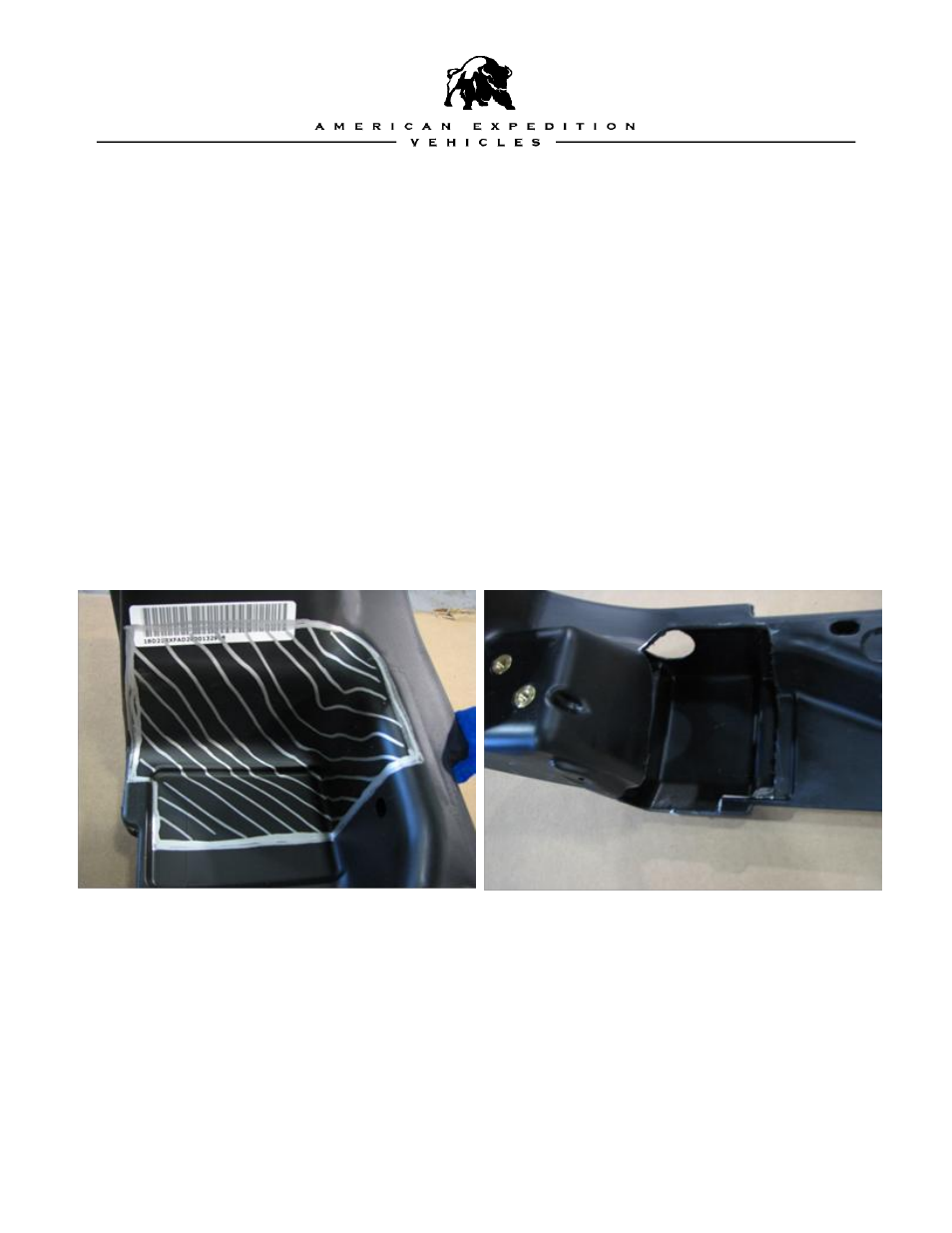
2. Working on the underside of the bumper, using a grey marker, markup the bumper as
shown below. This is where you will cut to allow clearance for the Spindle Housing. Be
careful not to cut away too much or cut through the outer surface of the bumper. You can
trim later as necessary if you need more clearance. The trimming operation is best done
using a small reciprocating air saw or cut off wheel.
3. Cut out the Spindle Tube template provided. Turn the bumper right side up and locate
the template on the top surface of the bumper. You will see a distinct parting line on the
forward tangent of the bumper as indicated in the photo. Position the template along the
parting line and the rearward upper tangent. Secure to the bumper with masking tape.
Mark the center of the hole with a center punch
and drill using a 2 ¾” hole saw.