3 power supply communication card settings – Alpha Technologies AlphaNet Series External DOCSIS Analog User Manual
Page 20
20
745-419-C0-002, Rev. B
2.0
Transponder Installation, continued
2.3 Power Supply Communication Card Settings
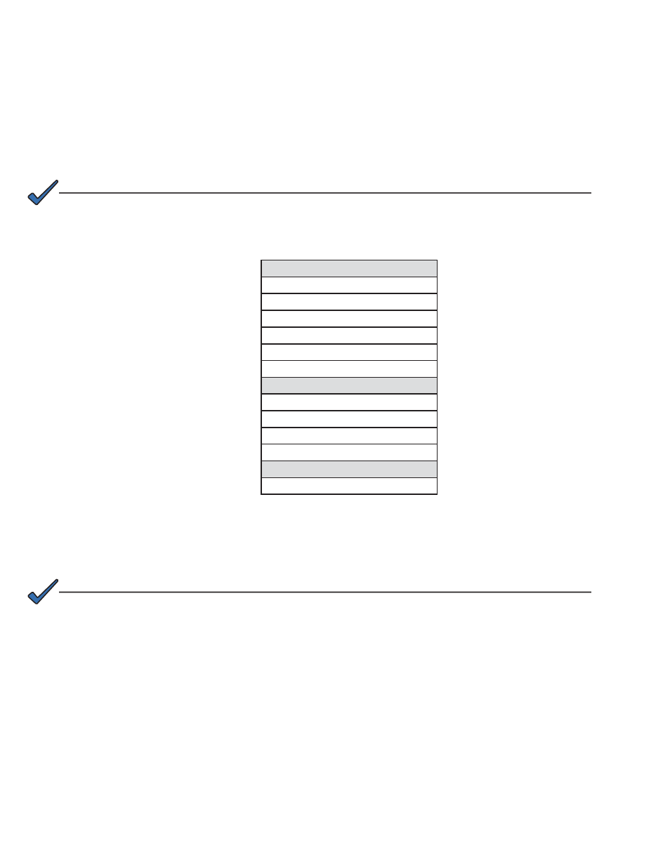
The power supply communication card settings determine the digital/analog setup and
scaling that affect how information is reported to your network management system. Refer to
your power supply’s communication card settings to be certain that your communication card
is set up correctly. The following table is for reference only.
Table 2-2, Power Supply Communication Card Settings
XM - USM
P1 = 2 & 3
P2, P4, P5, P6 = Closed
P3 = Open
P7 = 5V
P8, P9, P13 = 1 & 2
SW4 = 0
XM2 - USM2
SW1-1, 2, 6, 8 = On
SW2-1, 3, 4 = On
JP1 = C & 1
JP2 = 1 & 2
XM2 - USM2.5
SW1-1, 2, 6 = On
NOTE:
Output Current switch settings are determined by the output current capability of the power supply and should
be setup accordingly. See your power supply user manual for setting details.
• USM:
N/A
•
USM2:
SW1-3 = Output #1, SW1-4 = Output #2
•
USM2.5:
SW1-3 = Output Current Scaling, 15A or 22A
NOTE:
RPM-AM boards marked 700-019-28, 700-019-31, and 700-019-40 are compatible with the DOCSIS HMS
Analog Transponder.