Alpha Technologies AlphaNet Series External DOCSIS Analog User Manual
Page 19
19
745-419-C0-002, Rev. B
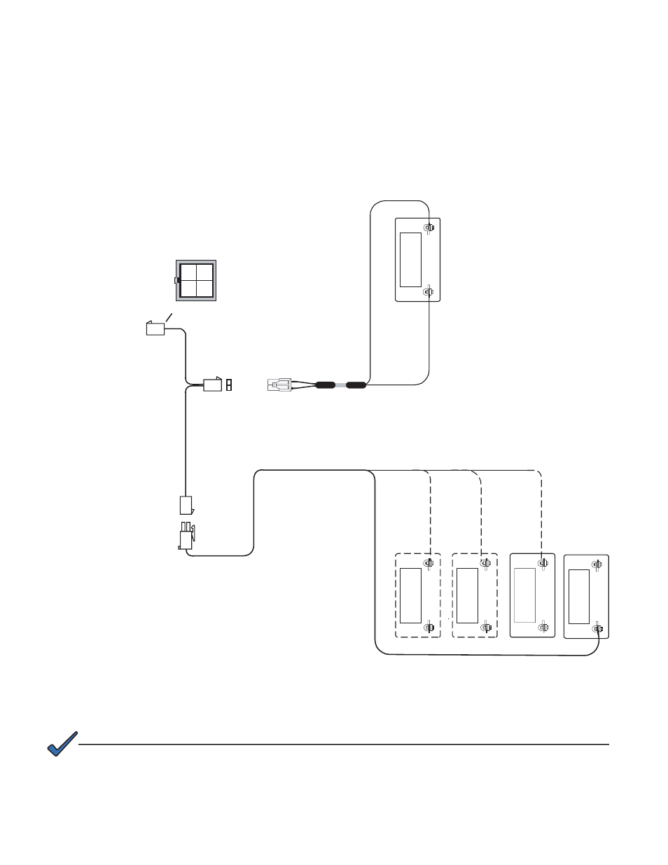
Fig. 2-4, Aux Power and Generator Ignition Battery Connectors
2.0
Transponder Installation, continued
2.2
Battery Sense Cable and Aux Power Connections, continued
Use the Aux Power connector to connect the ignition battery sense and auxiliary power
connections when the battery strings are located more than 15 feet from the transponder. The
Generator Ignition Battery Sense cable must be connected as shown below. Connect the Aux
Power connector where the red and black cables leading to the power supply are connected.
Pin 3 AUX POS connects to the last positive terminal in the string. This may vary depending on whether a
24V, 36V, or 48V string is used.
4A
POS
NEG
3A
POS
NEG
2A
POS
NEG
P
in
3
-
A
U
X P
O
S
P
in
4
-
A
U
X
NE
G
Back of Plug
1A
POS
NEG
P
in 2
- G
E
N
P
O
S
P
in 1
- G
E
N
NE
G
1
2
3
4
1A
POS
NEG
24V S
tri
n
g
36V
St
ri
n
g
48V S
tri
ng
2
1
Ignition Pos.
Ignition Neg.
Wire
Entry
View
Generator Ignition Battery Sense
Alpha P/N 875-038-20 (11’)
To DOCSIS
Transponder
Optional
Auxiliary
Power
NOTE:
Alpha P/N 874-976-20
Optional Generator Ignition Battery Sense
Alpha P/N 875-038-20 (11')
- AlphaCell GelCell Series (32 pages)
- FXM 650, 1100, 2000 UPS (96 pages)
- Cordex 48-1.2kW (68 pages)
- Radium MiniBay (57 pages)
- Fiber Backhaul Enclosure (FBE) (19 pages)
- FBE2322 Enclosure System (38 pages)
- FlexNet PMR, GMR Series (49 pages)
- Te25xh (38 pages)
- FlexNet MPS48-12M - Technical Manual (33 pages)
- FlexNet MPS48-12M - Quick Start Guide (2 pages)
- FlexNet ELPM 300-48D (25 pages)
- FlexNet FMPS (40 pages)
- FlexPoint AX Series (34 pages)
- FlexPoint FPR1207-F - Technical Manual (18 pages)
- FlexPoint FPR1207-F - Quick Start Guide (2 pages)
- AlphaGen PN-6x-T 7.5kW 48VDC - Installation and Operation Manual (79 pages)
- AlphaGen CE-3x2 5K-T 48Vdc (95 pages)
- AlphaGen PN-6x-T 7.5kW 48Vdc (95 pages)
- AlphaGen 3.5_5.0kW Kohler COM5 (80 pages)
- Security Bar Field For UPE-3, UPE-6, UPE-M3, UPE-M6, PN Series and CE Series (2 pages)
- AMPS80 HP (116 pages)
- 255A Bypass Switch (24 pages)
- AMP24 HP (108 pages)
- FXM350_Micro350 UPS (112 pages)
- CFR 600, CFR 600XT, CFR 1000 (70 pages)
- BPS Series Bypass Switch (36 pages)
- CFR Intelligent Interface Device (54 pages)
- CFR Redundant Control Unit (23 pages)
- CFR 5000, CFR 5000RM (88 pages)
- CFR 3000, CFR 3000RM (86 pages)
- CFR 1500, CFR 1500RM (83 pages)
- CFR 1500, CFR 2000, CFR 2500, CFR 3000 (76 pages)
- Continuity: 1000_2000_3000 (48 pages)
- Continuity Battery Pack (20 pages)
- Continuity: 6K_10K (52 pages)
- Micro, Micro XL, Micro XL3 UPS (99 pages)
- Micro Secure UPS (80 pages)
- Te17 (32 pages)
- Te45 (68 pages)
- Te41, 48V (76 pages)
- Te41, 24V (72 pages)
- Te43 (60 pages)
- AlphaGuard AG-CMT Installation (2 pages)
- AlphaGuard AG-CMT-3SC_4SC-P (2 pages)
- Digital Midtron DM-3200 AT (2 pages)