3 battery testing – Alpha Technologies CFR 1500, CFR 2000, CFR 2500, CFR 3000 User Manual
Page 61
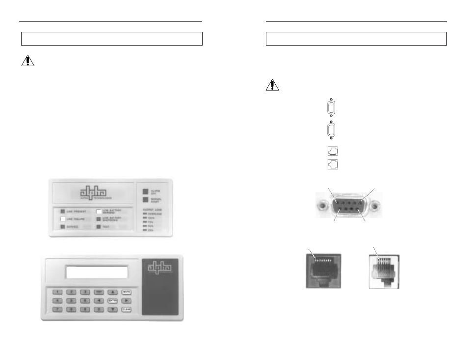
2. FEATURES
2.5 Communication / Interface Options,
continued
11
Pin 1
Pin 1
RJ-45
(External Alarms)
MMJ
(External IID)
Fig. 5
CFR-UPS Connector Identification and Pin-out
Rear Panel Connectors:
Below are the various communication connectors as they appear on the back of
the CFR-UPS. The photographs show the pin numbering for the different connector
types.
NOTE: Use only fully shielded cables to make connections to any of the
DE-9 connectors (RS-232 port or LAN interface).
Pin 1
Pin 5
Pin 6
Pin 9
DE-9 Connector (RS-232 and LAN)
RS-232 Serial Connector
External Alarms Connector
External IID Connector
LAN Interface Connector
6.3 Battery Testing
To determine the maximum amount of battery run time available,
run this test at least once a year. The length of the test can vary from
several minutes to many hours and should not be done during critical
applications. Since the test discharges the batteries, backup power may
not be readily available (for several hours) in the event of a utility power
failure.
1. Unplug the AC line cord from the wall receptacle. The front panel “LINE
FAILURE” LED will come ON. Make a note of the START time.
2. When the CFR reaches LOW BATTERY WARNING, record the time.
Subtract the START time to determine the actual safe run time. To cancel
the test, plug the AC line cord back into the wall receptacle.
3. To determine the reserve time available, allow the UPS to continue until it
reaches LOW BATTERY SHUTDOWN. Warning: This will cause the
load to go down. Make a note of the time. Subtract the LOW BATTERY
WARNING time to determine your available reserve time.
4. Switch the load OFF. Plug the AC line cord back into the wall receptacle.
The “LOW BATTERY WARNING” LED will remain ON until the batteries
are partially recharged. Switch the load ON, one device at a time. To
determine recharge time, subtract the time you resumed LINE PRESENT
operation from when the “LOW BATTERY WARNING” LED goes OFF.
54
Fig. 35 - Standard Interface Device
Fig. 36 - Intelligent Interface Device
ALPHA TECHNOLOGIES
05-07-96 08:02:10
LINE PRESENT
LINE FAILURE
LOW BATTERY
WARNING
SHUTDOWN
SERVICE
6. MAINTENANCE