Alpha Technologies CFR 1500, CFR 2000, CFR 2500, CFR 3000 User Manual
Page 39
4.2 Using the Standard Interface Device,
continued
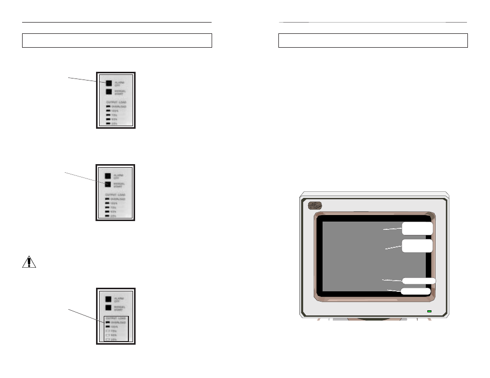
Alarm Off Switch
The switch cancels the audible LOW BATTERY WARNING alarm. The alarm
remains disabled until line power is restored and the batteries are recharged.
Fig. 27
Manual Start / ( old to Test) Switch
The switch is used to start the UPS from battery power whenever AC line power is
not available (“LINE PRESENT” LED OFF). The switch can also be used to test the UPS’
backup capabilities (“LINE PRESENT” LED ON) without interruption to the load.
Fig. 28
Output Load Display
The green “25%, 50%, 75%, and 100%” LEDs indicate the loading on the
UPS. Whenever the output load exceeds the rated output of the UPS, the
red “OVERLOAD” LED lights.
NOTE: Each successive LED lights depending upon the load. If the
UPS has a 75% load (displayed), then the 25%, 50% and 75% LEDs
will light. DO NOT EXCEED THE OUTPUT RATING OF THE UPS.
Fig. 29
32
4. OPERATION
ALARM OFF
Switch
MANUAL START
Switch
OUTPUT LOAD
LEDs
5. RS-232 TERMINAL COMMUNICATION
33
5.1 Remote RS-232 Operation
Introduction:
This section of the manual describes how to monitor, control and calibrate the
CFR-UPS using RS-232 ASCII commands and how to navigate through the program
using the menu structure.
The RS-232 serial interface is designed to work with terminal emulation software
in an interactive mode. Various parameters and commands may be accessed either
through the menus or by typing the number associated with the desired functions.
See section 5.3.
RS-232 menus have a hierarchical format. The top level menu, which is also
called the OPENING MENU, can be accessed by pressing the ENTER key (which
sends a carriage return character). This menu lists the numbers for accessing other
sub-menus plus displays the current LINE status and pending ALARM conditions.
The figure below shows the typical opening menu screen which displays the
menu options 1 through 7 followed by status and alarm messages. The INPUT LINE
shows the current status of the AC line which may be PRESENT; FAILURE; or TEST
MODE. The ALARMS message lists all current alarms. For a complete description
of alarms refer to section 5.12.
Fig. 30
Opening Menu
To display the System Parameters screen, type "1" and press ENTER.
Alpha Technologies
- CFR
Micro Serial#00000000
Opening Menu
1 System Parameters
2 Input Parameters
3 Output Parameters
4 Battery Parameters
5 User Parameters
6 -not available-
7 Maintenance Parameters
Input Line - Present
Alarms -
SERVICE2: SERV CODE 3
CFR-UPS Micro
Serial No.
Available Menu
Items (1-7)
AC Line Status
Alarms