Alpha Technologies CFR 1500, CFR 2000, CFR 2500, CFR 3000 User Manual
Page 14
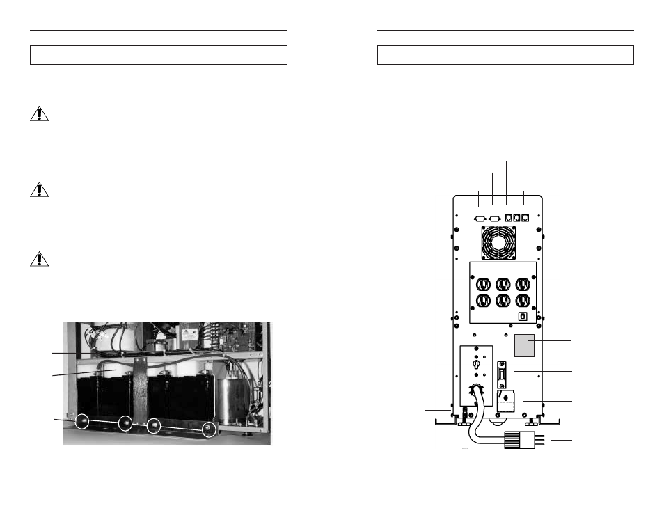
2. FEATURES
2.3 CFR Rear Panel
7
Fig. 2
CFR 1500, CFR 2000, CFR 2500, and CFR 3000 Rear Panel
11. Exhaust Fan
The UPS contains a rear panel exhaust fan to ensure maximum cooling protection
during all modes of operation.
12. OUTPUT Receptacle Plate
The load (equipment to be protected) connects to the rear panel output
receptacles. Styles vary depending upon country, frequency and voltage.
13. AC OUTPUT Circuit Breaker
The resettable breaker provides addional output protection to the load.
6
7
8
9
10
11
12
13
5
3
4
2
1
6. MAINTENANCE
58
6.5 Internal Battery Replacement,
continued
CFR 3000(E) Internal battery replacement procedure
IMPORTANT: READ THE SAFETY PRECAUTIONS LOCATED AT THE FRONT OF
THE MANUAL BEFORE PROCEEDING.
NOTE: All references to left and right are made facing the front of the CFR
1. Remove power from the CFR (Section 4)
2. Remove the CFR front panel and cover (Section 6.4)
3. Make a note of the battery orientation and cable connections. Carefully remove
the
BLACK (negative) wire from the negative (left) terminal of the rear battery.
4. Remove the RED (positive) wire from the positive (right) terminal of the
front
battery.
NOTE: The BLACK (negative) wire must be disconnected before removing
the RED (positive) wire.
5. Remove the BLACK (jumper) wires from the remaining batteries.
6. Remove the eight white foam blocks.
7. Remove the four bolts holding the right stabilizer and remove the stabilizer.
8. Carefully remove the center two batteries from the side of the CFR chassis. Slide
the remaining batteries to the middle and remove.
WARNING: Do not let the battery terminals contact the chassis.
9. Place new batteries into the UPS in reverse order of steps 1-8. Test the UPS for
proper operation before connection of the load.
Fig. 39
CFR 3000 Battery location
7
6
4