2 using the standard interface device – Alpha Technologies CFR 1500, CFR 2000, CFR 2500, CFR 3000 User Manual
Page 35
28
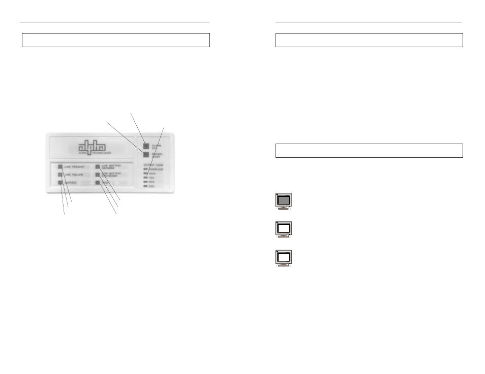
4.2 Using the Standard Interface Device
Fig. 17
Standard Interface Device
The Standard Interface Device displays vital UPS operating parameters and has
the ability to self-test the UPS at the touch of a button. When used in conjunction with
the CFR's rear-panel “Form-C” contact closures, UPS status information can be sent
directly to a Local Area Network (see section 2.5).
4. OPERATION
LINE PRESENT LED
Manual Start (Hold to Test) Switch
Alarm OFF Switch
LINE FAILURE LED
OUTPUT LOAD LEDs
TEST LED
LOW BATTERY WARNING LED
SERVICE LED
LOW BATTERY SHUTDOWN LED
5. RS-232 TERMINAL COMMUNICATION
37
5.4 Menu Commands Overview,
continued
Calibrating the CFR
The CFR-UPS may be calibrated using two sets of parameters - Maintenance
Parameters (commands “70” to “79”) and Service Parameters (commands “80” to
“89”). Maintenance parameters allow you to customize the CFR detection and
warning levels. There should be no need to change these setting unless wider or
narrower detection tolerances are required.
Transmitting Unsolicited Alarms
The UPS can automatically transmit alarm messages (in ASCII format) to notify
a status change or a power problem as it occurs. You can enable or disable this
option by using commands “510” and “509” respectively.
5.5 System Parameters
The “SYSTEM PARAMETERS” screen provides UPS battery temperature
information and manual initiation and termination of SELF TEST.
Battery Temperature
Displayed in degrees C, Ambient Temperature is measured inside the
UPS
in the vicinity of the battery compartment.
Start Test
Self Test can be initiated by selecting this menu. The test duration default
is 60 seconds.
Stop Test
Self Test can be terminated prior to the full duration of the test run time.
1
11
12