Abus - das gute gefühl der sicherheit – ABUS FTS 206 W AL0089 User Manual
Page 4
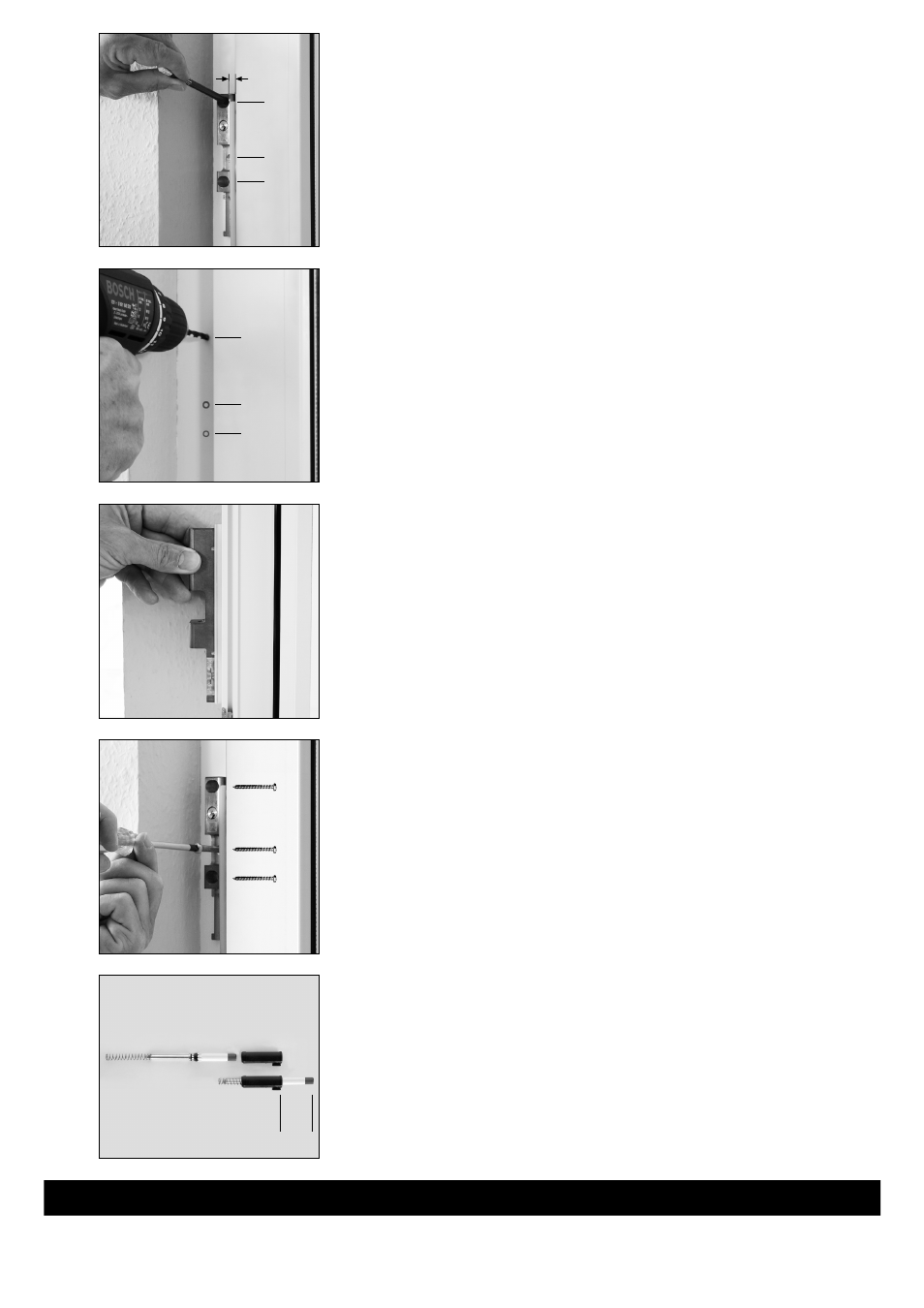
Montage / Installation / Installation / Montage / Montaggio
D
Rahmenleiste positionieren. Bohrlöcher A + B anzeichnen.
> 3 mm < Abstand.
Hilfsmittel: Unterlage für Rahmenleiste 2 mm einschließlich Nocken = 3 mm.
G
Position frame batten. Mark drill holes A + B.
> 3 mm < distance.
Accessories: Base for frame batten 2 mm including pins = 3 mm.
F
Positionner la lisière du cadre. Dessiner les trous de perçage A + B.
> 3 mm < ecart.
Aide: Support pour la lisière du cadre 2 mm, stries incluses = 3 mm.
n
Kader plaatsen. Boorgaten A + B markeren.
> 3 mm < afstand.
Hulpmiddel: Ondergrond voor kader 2 mm inclusief kam = 3 mm.
I
Posizionare la cornice del telaio. Segnare i fori A + B.
Distanza > 3 mm < .
Ausilio: Spessore per cornice del telaio 2 mm compresa camma = 3 mm.
390256 9
/06
ABUS - Das gute Gefühl der Sicherheit
www.abus.com
D
Technische Änderungen vorbehalten. Für Irrtümer und Druckfehler keine Haftung. ABUS © 2006
G
Subject to technical alterations. No liability for mistakes and printing errors. ABUS © 2006
F
Nous nous réservons le droit de toutes modifications techniques. Nous n’assumons aucune responsabilité pour des erreurs ou défauts d’impression éventuels
. ABUS © 2006
n
Technische wijzigingen voorbehouden. Geen aansprakelijkheid voor vergissingen en drukfouten
. ABUS © 2006
I
Ci si riservano modifiche tecniche. Per errori e refusi di stampa non ci si assume alcuna responsabilità
. ABUS © 2006
D
Löcher A + B vorbohren (Holz und Kunststoff ohne Metalleinlage).
In Alu und Kunststoff mit Metalleinlage siehe Bohrtabelle.
G
Pre-drill holes A + B (wood and plastic without metal ply).
In aluminium and plastic with metal ply see drilling chart.
F
Préforer les trous A + B (bois ou plastique insertion en métal).
Dans se l’alu et du plastique avec insertion en métal, voir tableau de perçage.
n
Gaten A + B voorboren (hout en kunststof zonder metalen versterking).
In alu en kunststof met metalen versterking, zie boortabel.
I
Sbozzare i fori A + B (legno e plastica senza inserto metallico).
In caso di alluminio e plastica con inserto metallico vedi la tabella di foratura.
D
Rahmenleiste eventuell mit Kunststoffunterlagen ausgleichen.
Bei Falzdicke:
18 mm
19 mm = 1 mm Unterlage
keine
Unterlage
25 mm = 7 mm Unterlage
G
If need be compensate for frame batten with plastic underlays.
With rabbet
18 mm
19 mm = 1 mm underlay
thickness:
no
underlay
25 mm = 7 mm underlay
F
Egaliser la lisière du cadre, éventuellement avec un support en plastique.
Pour une
18 mm
19 mm = support de 1 mm
épaisseur pas
de
de plis:
support
25 mm = support de 7 mm
n
Kader eventueel effenen met onderlaag in kunststof.
Bij sponning-
18 mm
19 mm = onderlaag van 1 mm
dikte:
geen
onderlaag
25 mm = onderlaag van 7 mm
I
Eventualmente equilibrare la cornice del telaio con spessori di plastica.
Con spessore
18 mm
19 mm = 1 mm di spessore
dell’aggraffatura: nessuno
spessore
25 mm = 7 mm di spessore
D
Rahmenleiste anschrauben
G
Screw on frame batten
F
Viser la lisiére du cadre
n
Kader vastschroeven
I
Avvitare la cornice del telaio
D
Druckstifteinheit falls demontiert wieder vormontieren.
G
If pressure pin unit disassembled pre-assemble again.
F
Prémonter l’ensemble de chevilles de pression, s’il a été démonté.
n
Indien de drukstift gedemonteerd werd, ze opnieuw monteren.
I
Se smontata, premontare l’unità del perno a pressione.
B
A
B
Abb. / fig.
schéma
afb. / ill. 1
B Ø 3,5
A Ø 4,0
B Ø 3,5
Abb. / fig.
schéma
afb. / ill. 2
Abb. / fig.
schéma
afb. / ill. 3
3 mm
ca.
40
mm
Abb. / fig. / schéma / afb. / ill. 5
Abb. / fig.
schéma
afb. / ill. 4
4,8 x 50
5,5 x 50
4,8 x 50