Description, Connections – ABUS SE1010 Key switch incl. ABUS quality cylinder User Manual
Page 7
7
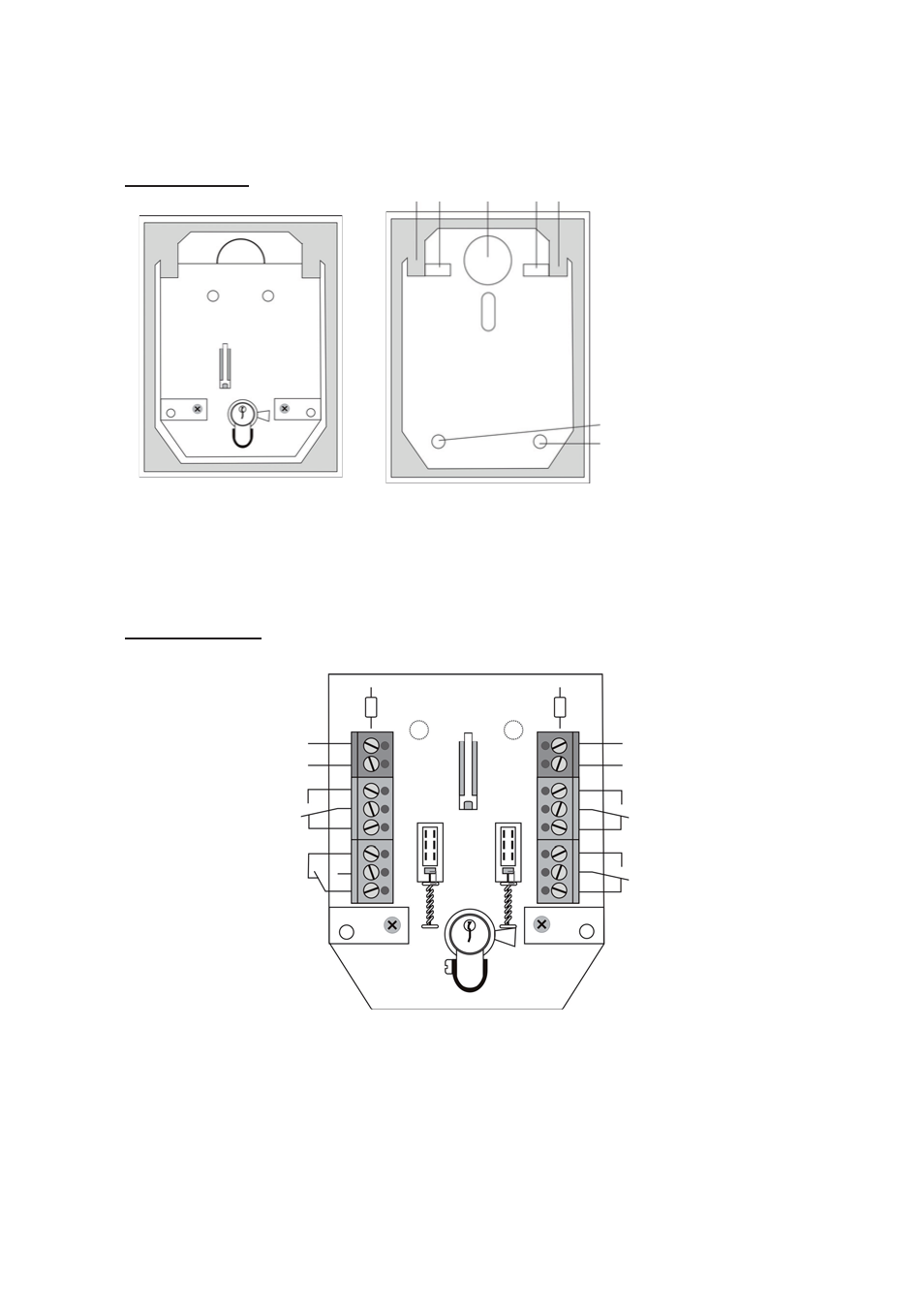
Description
Connections
2
2
Fig. 1 Casing open
(with PCB)
Fig. 2 Casing without PCB
1 PCB holder
2 Wall fixing
3 Cable hole
Note:
The switch position described applies when the cover is open.
Ground for LED (yellow)
Switch S2
12V for LED
NO
COM
NC
NO
COM
NC
S2
S1
NO
COM
NC
NC
NO
COM
Tamper
contacts
Switch S1
12V for LED
Ground for LED (red
)
1 2
2
3
1
This manual is related to the following products:
See also other documents in the category ABUS For Home:
- AZ4000 Terxon SX Alarm Control Panel Installation (294 pages)
- AZ4000 Terxon SX Alarm Control Panel Operating instructions (74 pages)
- BW8000 Wired motion detector (2 pages)
- SG1681 Flashing light and siren (12 pages)
- FU7350 Opening detector, 2m, 2-core (4 pages)
- SG1800 Profiline sounder (40 pages)
- BW8010 Xevox Profi VdS motion detector (3 pages)
- AZ6301 Terxon PSTN dialer (189 pages)
- SG1250 Inside siren (19 pages)
- SG1650 Optic_acoustic combination signal transmitter (24 pages)
- AZ4150 Terxon MX Compact Alarm Control Panel Installation (484 pages)
- AZ4150 Terxon MX Compact Alarm Control Panel Operating instructions (82 pages)
- RM1100 12 V differential heat detector (16 pages)
- RM1000 12 V optical smoke detector (15 pages)
- MK2000 Opening detector, 5m, 2-core (2 pages)
- MK1010 Opening detector, 4 m, 4-core (4 pages)
- MK4200 Opening detector for steel doors (2 pages)
- MK4100 Door opening detector, with external field protection, 2m, 4-core (6 pages)
- MK4000 Door opening detector, 2m, 4-core (6 pages)
- RS1000 Bar switching contact (4 pages)
- BW8040 Xevox Triplex MW VdS motion detector (3 pages)
- BW8070 Xevox Pet motion detector (1 page)
- BW8030 Xevox Duplex MW VdS motion detector (3 pages)
- BW8090 Xevox 360 VdS (3 pages)
- BW8085 Wired motion detector 360 (2 pages)
- BW8060 Wall_ceiling mount (1 page)
- AZBW20000 Outdoor motion detector (88 pages)
- LS2060 Profiline infrared Light beam (43 pages)
- LS1020 Ecoline infrared light beam (2 pages)
- EM2000 Seismic alarm sensor (2 pages)
- FU7300 Potential-free glass breakage detector (4 pages)
- GB3010 Glass breakage detector 12 V (2 pages)
- GB2000 Acoustic glass breakage detector (2 pages)
- AZ4140 Relay board for the Terxon SX_MX_LX, 8 outputs (14 pages)
- AZ4290 Terxon 2WAY Module (156 pages)
- AZ4230 Terxon LX 8-zone Wired Extension (32 pages)
- AZ4250 Terxon LX 8-zone Wired Extension with PSU (32 pages)
- AZ4130 Terxon MX 8-zone Wired Extension (20 pages)
- AZ4120 Terxon MX 8-zone Wireless Extension (32 pages)
- FU2938 Compact Alerting (71 pages)
- SG1680 Xenon flashing light (4 pages)
- AZWG10000 Profiline GSM-Interface II (118 pages)
- AZWG10100 Speech module for GSM-Interface II (11 pages)
- AZ6302 Terxon GSM dialer (245 pages)