Elmo Rietschle L-BV7 User Manual
Page 31
© Gardner Denver Deutschland GmbH
31 / 64
610.48060.40.000
Commissioning
8.3
Operation with operating-liquid feed
See Fig. 9, Pg. 31; and Fig. 10, Pg. 31, as well as Fig. 11, Pg. 32 and Fig. 12, Pg. 32.
Proceed as follows here:
Method A:
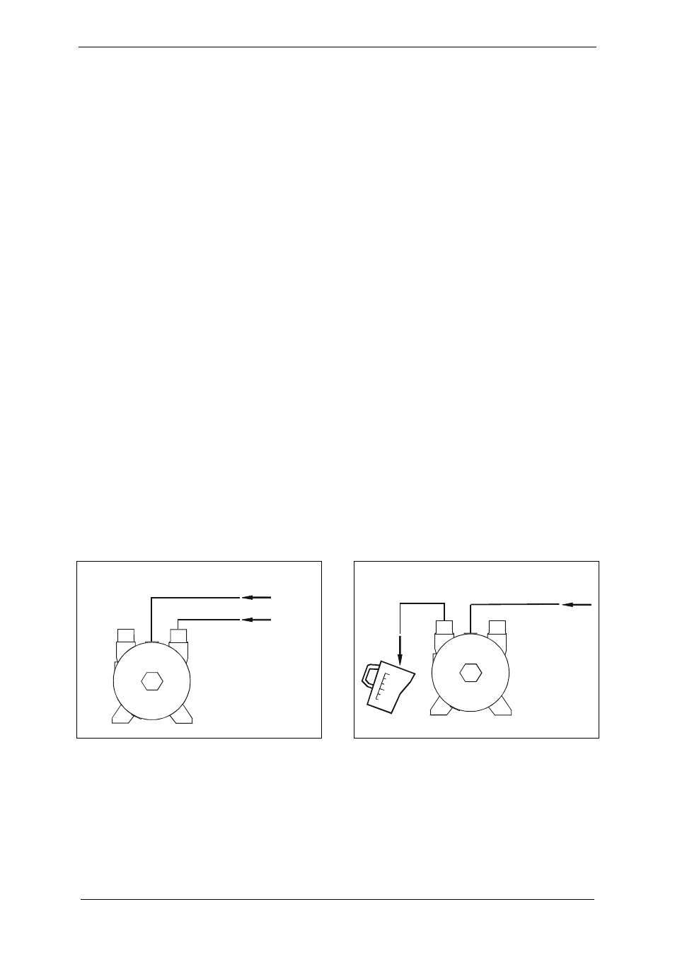
1) Set pre-pressure of operating liquid (Fig. 9,
Pg. 31):
Set a pre-pressure p
A
in the feed pipe for
the operating liquid (Item A) around
approx. 1 bar [14.5 psi] above the inlet
pressure p
B
in the inlet pipe (Item B).
2) Start up the unit:
For non-automatic operation (Fig. 11, Pg. 32):
Open the stop valve (Item 4) manually.
The operating liquid is fed in.
Switch on the unit.
For automatic operation (Fig. 12, Pg. 32):
Switch on the unit.
The solenoid valve (Item 4) opens
and the operating liquid is fed in.
Method B:
1) Start up the unit:
For non-automatic operation (Fig. 11, Pg. 32):
Open the stop valve (Item 4) manually.
The operating liquid is fed in.
Switch on the unit.
For automatic operation (Fig. 12, Pg. 32):
Switch on the unit.
The solenoid valve (Item 4) opens
and the operating liquid is fed in.
2) Check the operating-liquid flow rate:
with the flow meter (Fig. 11, Pg. 32, and
Fig. 12, Pg. 32, Item 2)
OR
by measuring the volume of operating liquid
per unit of time that exits at the discharge
connection with a graduated vessel
(Fig. 10, Pg. 31)
3) Set/correct the operating-liquid flow rate:
via the control valve (Fig. 11, Pg. 32, and
Fig. 12, Pg. 32, Item 3)
Nominal operating-liquid flow rate:
For nominal values, see Chapter 4.3,
"Operating conditions", Section "Nominal
operating-liquid flow rate", Pg. 17.
A
B
p = p + 1 bar
A
B
p = p + 14.5 psi
A
B
A
B
Fig. 9: Setting the operating-liquid flow rate:
Setting pre-pressure
Fig. 10: Setting the operating-liquid flow rate:
Measuring the volume with a graduated vessel
A Feed pipe for operating liquid
B Inlet
pipe
A Feed pipe for operating liquid
B Drain pipe for operating liquid