Gorman-Rupp Pumps 04E1-GHH 1076270 and up User Manual
Page 39
0 SERIES
OM−03688
MAINTENANCE & REPAIR
PAGE E − 14
NOTE
If the pump casing was removed, install the casing
O-ring and gasket (12 and 18) on the pump casing
studs. Carefully slide the casing over the shaft, and
secure it to the gearbox with the nuts (17).
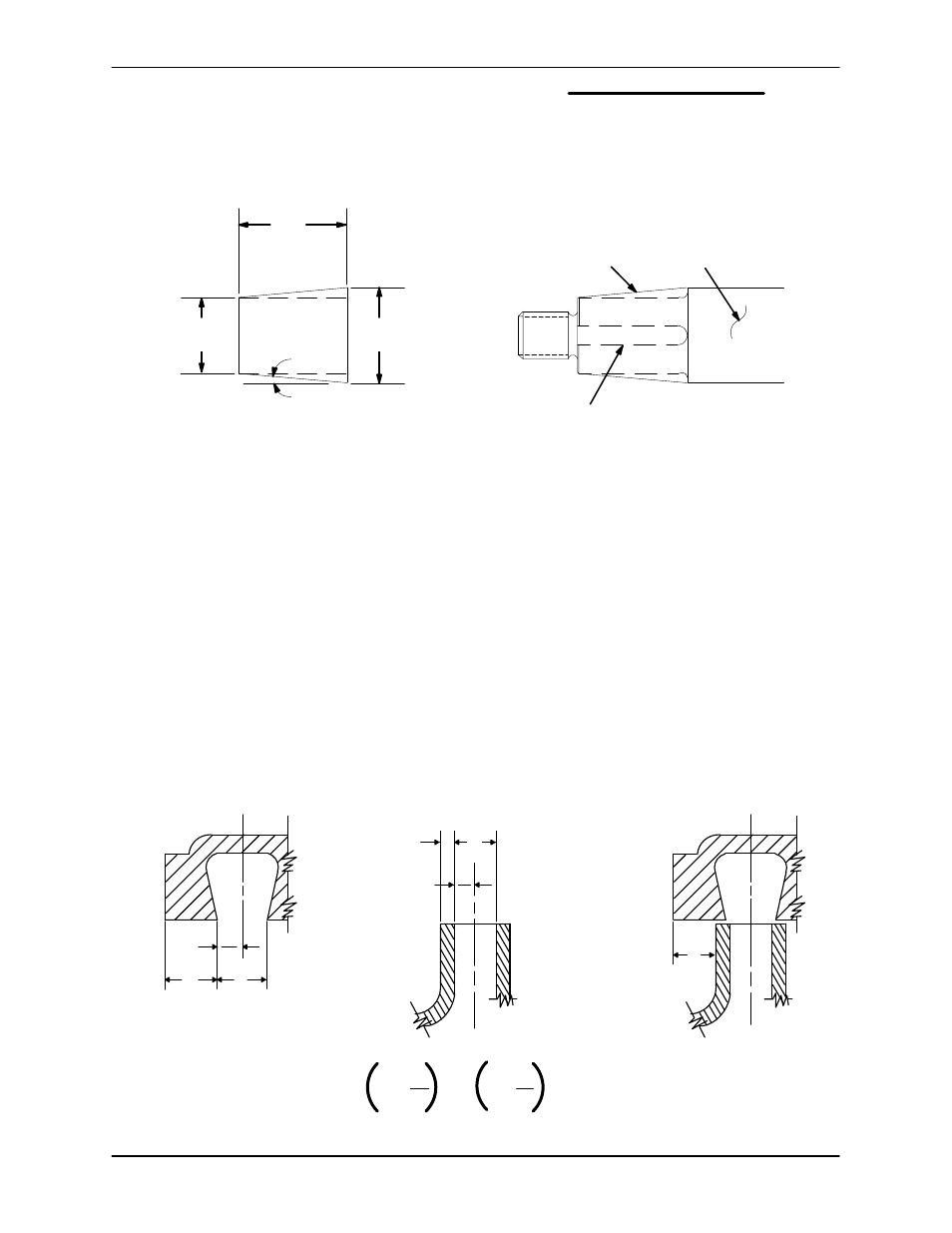
Install a tapered sleeve (see Figure 5) over the shaft
keyway to ease installation of the rotating portion of
the seal. This tool can be made from steel tubing or
pipe.
5
_ TAPER
(APPROX.)
SLEEVE
1.00 D
1.44
FINISH ALL OVER TO
BE 50 RMS OR LESS
ENDS TO BE SQUARE
AND PARALLEL
36,6 mm
25,4 mm
IMPELLER
SHAFT
SEAL
AREA
KEYWAY
1.252 D
31,8 mm
SLEEVE DIMENSIONS
SLEEVE INSTALLED
Figure 5. Seal Installation Sleeve
Lubricate the tapered sleeve and position it on the
shaft. Position the rotating portion of the seal (con-
sisting of the retainer, bellows and rotating ele-
ment) on the sleeve, and apply even pressure
against the shoulder of the seal retainer until the ro-
tating subassembly slides onto the shaft and the
seal faces contact. A push tube cut from a piece of
plastic tubing would aid this installation. The I.D. of
the tube should be approximately the same diame-
ter as the I.D. of the seal spring.
Remove the tapered sleeve and install the seal
spring.
Impeller Installation
Inspect the impeller and replace it if cracked or
badly worn.
For maximum pump efficiency, the impeller must
be centered within the volute scroll. Center the im-
peller by adding or removing adjusting shims (20).
To verify impeller positioning, measure the pump
casing and impeller as shown in Figure 6. Use
these measurements to calculate the required im-
peller location (dimension E). Add or remove im-
peller adjusting shims until dimension E is ob-
tained.
D
B
2
A
B
2
C
D
E
Step 2
Step 1
Step 3
A+
B
2
C+
D
2
E
=
−
Figure 6. Centering Impeller Within Volute Scroll