Gorman-Rupp Pumps 04E1-GHH 1076270 and up User Manual
Page 14
OM−03688
0 SERIES
PAGE B − 7
INSTALLATION
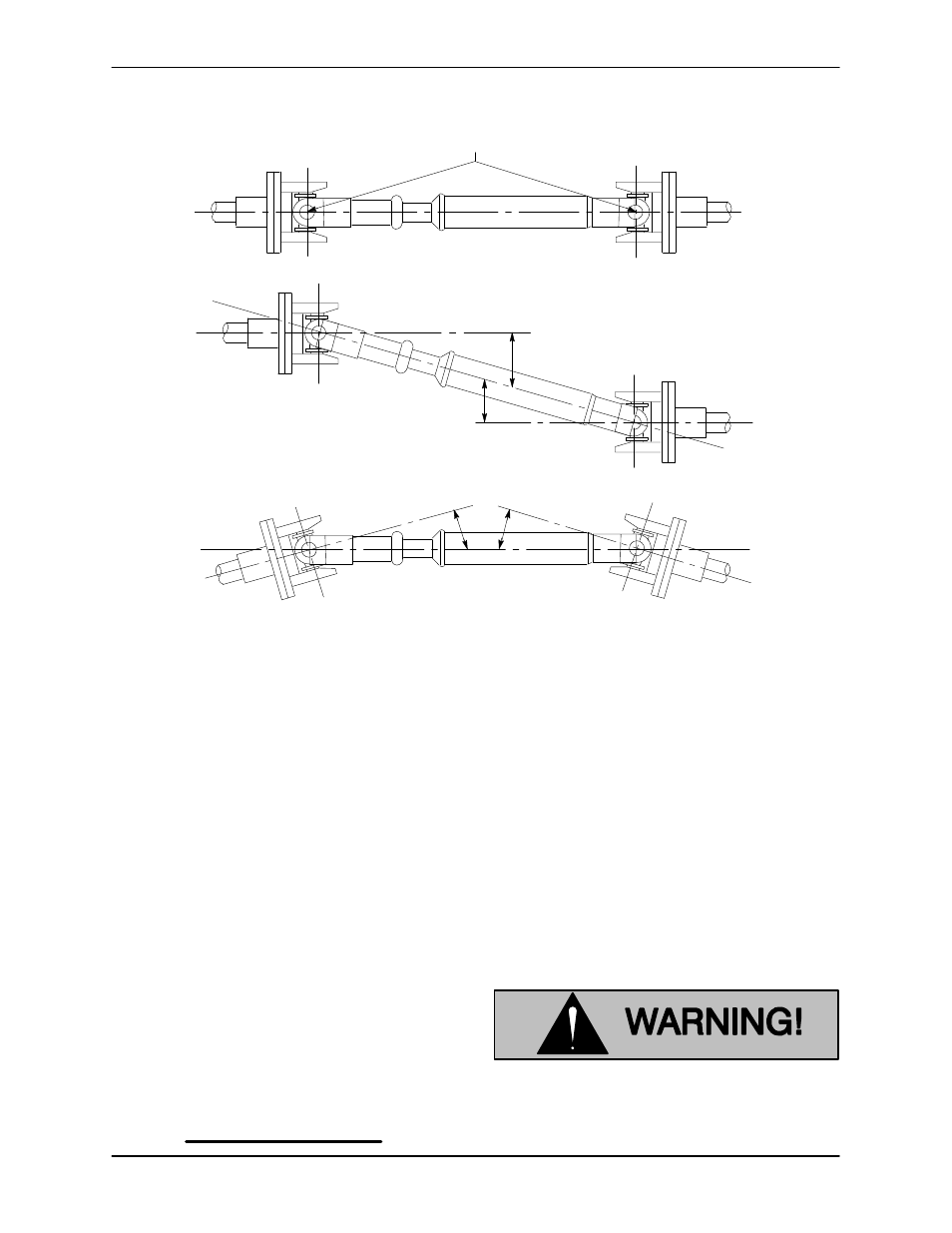
LUG ALIGNMENT
SHAFTS PARALLEL, ANGLES EQUAL
SHAFTS NOT PARALLEL, ANGLES EQUAL
LUGS MUST BE IN LINE, REGARDLESS
OF OPERATING ANGLE SHOWN BELOW
Figure 3. Drive Shaft Alignment
The alignment of the pump and its power source is
critical for trouble-free mechanical operation. Be-
fore checking alignment, make sure that the gear-
box mounting bolts are tight.
When connecting the universal joint drive shaft as-
sembly to a PTO unit, install, support, and align the
drive shaft in accordance with the manufacturer’s
instructions. The pump and the drive power source
are generally positioned so that shaft centerlines
are parallel and horizontal.
Make sure the horizontal and vertical joints are
equal. Limit the angles to 1 to 3
_ using a short
coupled joint, and less than 8
_ with a double joint
assembly. The maximum operating angle should
not exceed 15
_ (see Figure 3).
NOTE
Install a short coupled slip joint on the input side
and a double joint with slip on the output side of the
gearbox to attain the prescribed angles and elimi-
nate tensile stress on the shaft.
The input and output shafts should be completely
subassembled and checked for straightness and
balance before installation. Also check the univer-
sal joint yokes for proper alignment.
Check the direction of rotation of the PTO unit be-
fore starting the pump. The drive shaft must rotate
in the direction shown on the body of the pump,
gearbox, and/or decals, tags, and labels.
Gear Shift Connections
After the pump is mounted to the chassis, hook up
the air shift rod to the proper control stations.
Decals and tags vital to pump operation
were shipped loose with the pump.
These decals must be affixed in a promi-
nent place visible to the pump operator.