Gorman-Rupp Pumps 04E1-GHH 1076270 and up User Manual
Page 12
OM−03688
0 SERIES
PAGE B − 5
INSTALLATION
Due to the confined mounting location,
specialized equipment such as a transmis-
sion jack with custom brackets should be
used to lift and position the pump and
gearbox.
Mounting Location
The following factors must be considered when se-
lecting a mounting location for the pump.
a. Mounting brackets
b. Universal joint angles
c. Shift linkage
d. Piping
e. Ground clearance
f. Accessibility of pump and gearbox for service.
.
Any damage to the pump or gearbox resulting from
improper mounting and installation is not covered
by the Gorman-Rupp Warranty.
Mounting Brackets
The customer must furnish two cross members
which fit between the vehicle chassis side rails (see
Figure 2). They must be heavy enough to support
the weight of the pump assembly and provide easy
access for pump maintenance.
Secure the rear cross member rigidly to the pump
and gearbox using a fabricated mounting bracket
(customer-furnished). The mounting bracket must
fasten to the threaded holes located in the pump
casing above the pump suction, and in the top of
the gearbox housing. The bracket and cross mem-
ber must not obstruct pump operation or impede
removal of the pump casing during maintenance.
The rear cross member or mounting
bracket must not interfere with movement
of the air shift indicator shaft (located on
top of the gearbox). If necessary, drill a
1-inch (25,4 mm) diameter hole through
the cross member or bracket to provide
clearance.
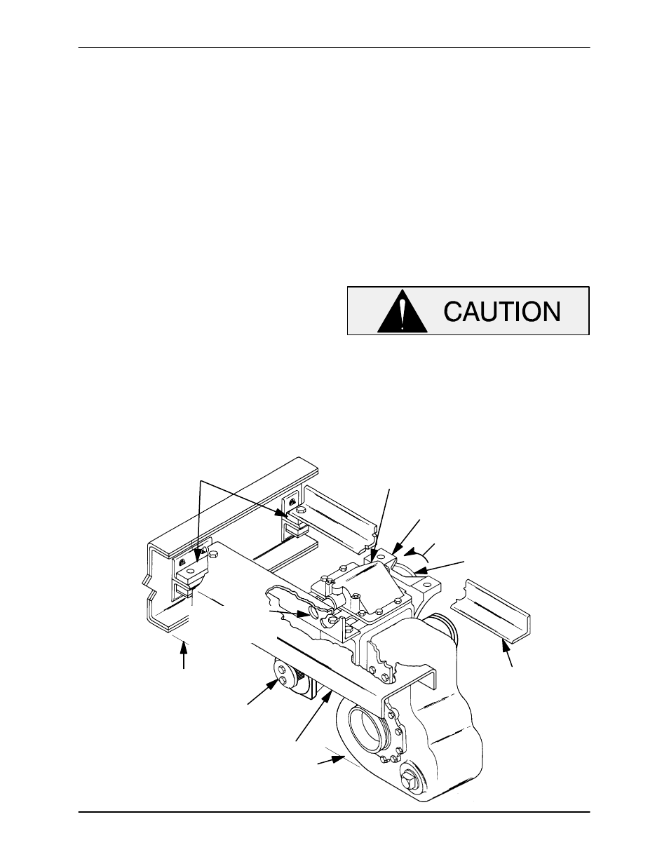
AIR SHIFT COVER
TRUNNION BRACKET
DRIVE INPUT FROM
TRANSMISSION
FRONT CROSS MEMBER
(SUPPLIED BY CUSTOMER)
REAR CROSS MEMBER
(SUPPLIED BY CUSTOMER)
OUTPUT TO REAR AXLE
(SHOWN WITHOUT FLANGES)
1" [25,4 mm] DIA.
HOLE FOR AIR
SHIFT POSITION
INDICATOR SHAFT
RUBBER MOUNTED
BY CUSTOMER
16.31"* [414,3 mm] APPROX.
ROAD CLEARANCE
29" * [736,6 mm] APPROX.
ROAD CLEARANCE
NOTE: DIMENSIONS MARKED WITH AN ASTERISK (*) MAY BE
ALTERED TO FACILITATE INSTALLATION OF UNIT
INPUT ROTATION FOR PUMP
Figure 2. Typical Pump Mounting on Vehicle Chassis