Gorman-Rupp Pumps 04E1-GHH 1076270 and up User Manual
Page 13
OM−03688
0 SERIES
PAGE B − 6
INSTALLATION
The drive input end of the gearbox is fitted with a
trunnion which prevents chassis frame twist from
being transmitted through the gearbox. Mount the
trunnion to the front cross member (not supplied)
to support the drive input end of the pump. When
mounting the trunnion, make certain that it will not
interfere with the input drive flange. The trunnion
mounting foot must be directed toward the input
flange.
Position the cross members and mounted pump
on the side rails of the chassis. The cross members
must be mounted with rubber or other vibration-
dampening material when secured to the side
rails.
Do not secure the cross members to the side rails
before establishing the exact location and position
of the air shift rod and shift indicator connections.
Be careful not to put the pump in a bind from front
to rear during mounting. Improper alignment could
result in bearing or gear failure, or gearbox break-
age (see Drive Shaft Alignment).
Drive Flanges
The input and output shafts on the gearbox (2-3/4
inch, 10-spline) are equipped with heavy-duty
Dana 1800 Series flanges. The shaft splines are
designed to produce a tight interference fit with the
drive flange. This fit is intentional to eliminate fret-
ting corrosion.
For instructions on installing or removing drive
flanges and universal joints, see the specific areas
in MAINTENANCE AND REPAIR, Section E.
DRIVE SHAFT AND
LINKAGE CONNECTIONS
Drive Shaft Alignment
To promote maximum universal joint and bearing
life, the universal joint angles must be kept to a
minimum. A joint angle of 1
_ is required for proper
needle bearing circulation, but excessive angles
cause accelerated wear and require a lower maxi-
mum operating speed (see Table 3).
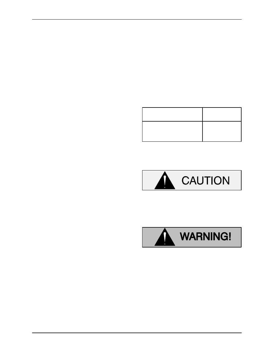
Table 3. Joint Angle/Maximum RPM
JOINT
ANGLE
MAXIMUM
SPEED
5
_
5000 RPM
6
_, 30’
4000 RPM
8
_
3000 RPM
Align the gearbox with the transmission and the
rear axle to obtain the optimum universal joint
angles. See Figure 3 for drive shaft alignment.
Be certain the rear axle position when the
vehicle is empty or fully loaded will not
cause excessive universal joint angles, or
cause the drive shaft slip joints to bottom
out.
When installing and/or aligning univer-
sal shaft assemblies, shut off the ve-
hicle ignition and remove the key to en-
sure that the pump will remain inopera-
tive.