Gorman-Rupp Pumps 04E1-GHH 1076270 and up User Manual
Page 15
OM−03688
0 SERIES
PAGE B − 8
INSTALLATION
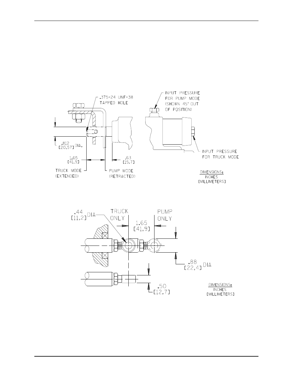
Proper operation of the gearbox air shift requires
air pressure of 70 to 140 psi (5,1 to 10,2 kg/cm
@)
and 1/4" air lines. The air line connection at the end
cap of the air cylinder is for vehicle operation, and
the air line connection at the top of the air shifter
cover is for pump operation. Seal all hose fittings
with Permatex" or equivalent compound.
When activated, the shifter rod travels through a
hole in the rear cross member. A customer-
supplied shift indicator (mechanical, electrical, or
air operated device) should be installed in this area
to indicate shifter mode to the pump operator. A
tapped hole is provided in the shaft for conve-
nience.
See Figures 4 and 5 for the approximate shaft trav-
el and hole size. See Figure 4, Section E for Air Shift
Kit parts.
Figure 4. Air Shifter Shaft Detail
Figure 5. Optional Manual Shifter
SUCTION AND DISCHARGE PIPING
Typical System Installation
Most petroleum handling vehicles perform both
fueling and defueling operations. This requires a
system utilizing flow-directing (FDF) valves, educ-
tors, related piping and safety accessories. Some
of the accessories are available from Gorman-
Rupp as optional equipment.
Refer to Figures 6 and 7 for illustrations of typical
piping systems used on refueling vehicles.