Cla-Val DBJ Series User Manual
Page 3
P a g e
2
DB O INSTALLATION
1.
The outer or inner
surface of the pipe
must be smooth and free of burrs and sharp edges. Before installing the valve, verify its
fit by measuring the ID or OD of the cuff and the ID or OD of the pipe.
2.
Slide the clamp(s) along the pipe or leave them on the valve cuff for DBO valves. Do not tighten until after the valve is in place.
3.
Slip a DBO evenly over the end of the pipe until the entire length of the valve cuff is in contact with the pipe. Ensure that
the check valve’s bill is oriented in a vertical position.
4.
After the check valve is properly positioned, install the clamp(s). Where 2 clamps are required, they should be rotated 90 degrees relative to
each other. This will ensure that even pressure is distributed around the cuff. A thin coat of mild lubricant or glycerine may be applied on
the inner surface(s) of the clamp(s). This will reduce the friction when tightening the clamp(s).
5.
Ensure that the valve is snug to the pipe and be careful not to over-torque the clamps.
a.
The recommended torque values for gear clamps 1-¾” and smaller is 3ft-lbs. For sizes larger than 1-¾” the torque value is 5 ft-lbs or as
otherwise noted by the Cla-Val Technical Department.
b.
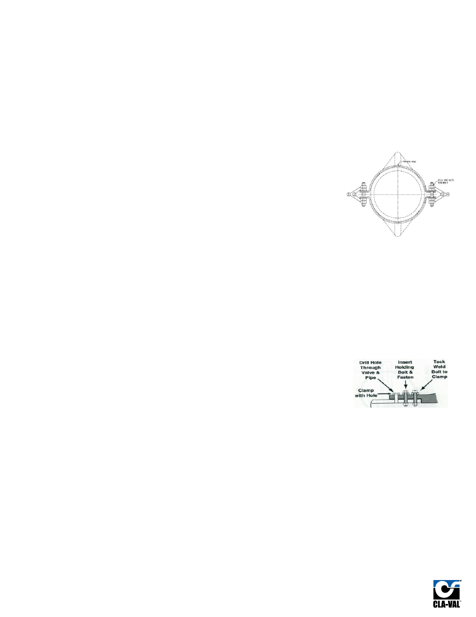
For larger DBO valves that do not use gear clamps, the inner sets of nuts (Figure 1 – nuts 2
and 3) clamp the valve to the pipe. These nuts should be tightened until the slack is removed
from the rubber cuff and the valve cuff is snug against the outside of the pipe. With a torque
wrench set at 10 ft-lbs, torque the nuts until a snug fit is achieved. This will ensure the valve
cannot be physically removed from the pipe. For valves 32” and up, a 20 ft-lbs torque setting
is required. The outer sets of nuts (Figure 1 – nuts 1 and 4) lock the first set of nuts in place.
This will prevent the clamps from loosening on the valve.
6.
DO NOT use a lubricant to aid in the installation of the valve onto or inside the pipe. It could cause
the valve to slip out of position.
7.
Metal clamps on large size check valves (12” and larger) are provided with drilled holes for anchor
bolts. These holes are used as a pattern for drilling through the rubber and the outfall pipe. These
anchor bolts should be installed 90 degrees to the clamp and may also be used on smaller valves
provided that this requirement is discussed prior to valve manufacture. See “Securing DBO Check Valves”
(below) for clarity.
NOTE: Debris caught under a check valve can potentially affect its operation. Therefore, ensure that there is approximately 6” of ground clearance
between the bill of the valve and the ground during and after installation.
Securing DBO Check Valves
Anchor bolts are recommended to further secure the check valve into position. Using the clamp(s) as a template, drill a hole(s) through the valve cuff
and through the pipe using a drill bit. Insert a stainless steel anchor bolt through the clamp hole, the cuff and the pipe and secure the anchor bolt
with stainless steel nut, and washers. Anchor bolts are not supplied with the valves since pipes vary in thickness. For installations that may not permit
the installer to access the inside or outside of the pipe (to place the nuts on the anchor bolts), simply place the anchor bolt(s) into the hole(s) and tack
-
weld the anchor bolt to the clamp, thus creating a pin(s) to hold the valve. Exercise caution to minimize heat and splatter near the check valve and
perform welding away from the joint wherever possible.
DBO
DBJ INSTALLATION
Note:
DBJ Split Body Design
-
Downstream gasket required (not supplied with check valve).
-
Do NOT install against raised-face flanges (only to smooth-face flanges).
1.
Remove all burrs or sharp edges from the pipe flange faces and wipe clean of oil, grease, etc.
For DBJ Split Body Design
- On the upstream flange of the duckbill check valve, (where the duckbill’s rubber flange will mate to the
upstream pipe flange), apply a thin coat of graphite or glycerine to the pipe flange face.
This will ease installation
and allow for easy
removal at a later date.
No upstream gasket is required between the rubber duckbill flange and the mating pipe flange.
2.
Lift the duckbill check valve into position, ensuring that the valve is oriented in the correct direction of flow, (i.e. the bill end should be on the
downstream side of the valve). Align the bolt holes of the pipe and check valve flanges and ensure the check valve’s bill is oriented in a
vertical position or as nearly vertical position as possible.
3.
After the duckbill check valve is in the correct position, push two (2) bolts through each of the mating pipe flanges/check valve flange to
ensure alignment. After the proper alignment has been obtained, install the remaining bolts and nuts.
For DBJ Split Body Design - On the upstream flange of the duckbill check valve, (where the duckbill’s rubber flange will mate to the
upstream pipe flange) - tighten all flange bolts in a criss-cross pattern similar to the one shown in Figure 2 to the maximum torque
recommended in Figure 3.
4.
Do not weld near the Check Valve.
Figure 1
www.cla-val.com