Cla-Val DBJ Series User Manual
Page 2
www.cla-val.com
P a g e
1
OPERATION
Cla-Val Duckbill Check Valves are custom made and are intended for specific applications. They are designed to
respond to criteria unique to their purpose, such as line pressure, backflow pressures, and chemical compatibility.
Should the conditions be altered or changed significantly, it could affect the normal operation of the valves.
Cla-Val Duckbill Check Valves operate
based on differential pressure.
When the line pressure (at the valve inlet)
exceeds the backpressure (at the valve outlet), the valve opens and flow is created. When the backpressure
exceeds or overcomes the line pressure, the bill of the valve seals shut, thereby preventing any backflow from
occurring.
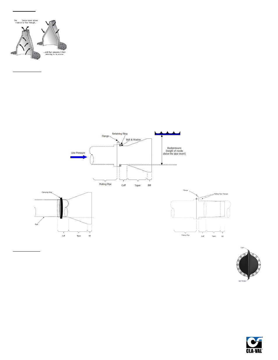
TERMINOLOGY (refer to diagrams below)
Cuff:
The round portion of the valve from taper to the flange (where applicable).
Taper:
The taper transforms the round shape of the valve cuff to the vertical shape of the valve bill. Reinforcement in the taper is customized to suit each
application’s expected inlet pressures and backpressures.
Bill:
The outlet end of the valve. The bill contorts to allow flow through the valve yet closes tight during ‘no flow’ or reverse pressure conditions. The
bill can be straight or curved, depending on the application.
Tube:
The inner surface. This is constructed using an elastomer that is most suitable for the process fluid.
Cover:
The outer surface of the valve. This is made from an elastomer that is most suitable for the external environment.
Retaining Ring:
Supplied with the valve, the duckbill flange is ‘sandwiched’ between the mating pipe flange and the retaining ring.
Clamps:
Supplied with the valve, the duckbill cuff is squeezed between the mating pipe and the clamp(s) (inside or outside of the pipe).
Line Pressure:
The fluid pressure applied to the valve inlet (used to open the valve).
Backpressure:
The fluid pressure exerted on the valve outlet. It is usually measured in feet or metres of fluid above the pipe invert.
DBF/DBJ
DBO/DBJ
DBI
INSTALLATION
Ensure that pipelines have been depressurized prior to installation, removal, or servicing the check valve. For best performance,
bills should be installed as close to the vertical position as possible. In cases where clearance below the pipe outlet is minimal, the
duckbill should be rotated only enough as required to avoid contact with the ground. Please contact your Cla-Val representative
or the Cla-Val factory at 800.932.6326 directly to discuss this application.
DBF/DBI INSTALLATION
1.
Do NOT install against raised-face flanges (only to smooth-face flanges). Remove all burrs or sharp edges from the pipe flange faces and
wipe clean of oil, grease, etc. Apply a thin coat of graphite or glycerine to the pipe flange face. This will ease installation and allow for easy
removal at a later date.
2.
Lift the duckbill check valve into position and align the bolt holes of the pipe flange, check valve flange and the retaining ring. Ensure that the
check valve’s bill is oriented in a vertical position.
3.
After the duckbill check valve and retaining ring (where applicable) are in the correct position, push two (2) bolts through to ensure
alignment. After the proper alignment has been obtained, install the remaining nuts and bolts using washers at the split holes (if the Check
Valve comes with a retaining ring).
4.
Use two wrenches when installing the Check Valve. Tighten all flange bolts in a criss-cross pattern similar to the one shown in Figure 2 to the
maximum torque recommended in Figure 3.
5.
Do not weld near the Check Valve.
DBF