01 ul – Cla-Val 90-21 Technical Manual User Manual
Page 9
100-01 UL
Diaphragm Check (#1 )
1. Shut off pressure to the 90-21 valve by slowly closing upstream and
downstream isolation valves.
CAUTION: The valve cannot be serviced under pressure. Where
there are no isolation valves, It will be necessary to deactivate the sys-
tem.
2. Disconnect or close all pilot control lines to the valve cover and
leave only one fitting in highest point of cover open to atmosphere.
3.With the cover vented to atmosphere, slowly open upstream isola-
tion valve to allow some pressure into the valve body. Observe the
open cover tapping for signs of continuous flow. It is not necessary to
fully open isolating valve. Volume in cover chamber capacity chart will
be displaced as valve moves to open position. Allow sufficient time for
diaphragm assembly to shift positions. If there is no continuous flow,
you can be quite certain the diaphragm is sound and the diaphragm
assembly is tight. If the fluid appears to flow continuously
this is a good reason to believe the diaphragm is either damaged or it
is loose on the stem. In either case, this is sufficient cause to remove
the valve cover and investigate the leakage. (See “Maintenance” Sec-
tion for procedure.)
COVER CHAMBER CAPACITY
(Liquid Volume displaced when valve opens)
Valve size (inches)
Displacement
Gallons
Liters
1 1/4
.020
.07
1 1/2
.020
.07
2
.032
.12
2 1/2
.043
.16
3
.080
.30
4
.169
.64
6
.531
2.0
8
1.26
4.8
10
2.51
9.5
Freedom of Movement Check (#2)
4. Determining the Valve’s freedom of movement can be done after
all pressure is removed from the valve.
After closing inlet and outlet isolation valves and bleeding pressure
fro the valve, check that the cover chamber and the body are tem-
porarily vented to atmosphere. Insert fabricated tool into threaded
hole in top of valve stem, and lift the diaphragm assembly manu-
ally. The tool is fabricated from rod that is threaded on one end to
fit valve stem and has a "T" bar handle of some kind on the other
end for easy gripping. (See chart in step 4 of "Disassembly" Sec-
tion.)
Place marks on this diaphragm assembly lifting tool when the valve
is closed and when manually positioned open. The distance be-
tween the two marks should be approximately the stem travel shown
in the chart.
If the stroke is different than that shown, there is a good reason to
believe something is mechanically restricting the stroke of the valve.
The cover must be removed, and the obstruction located and re-
moved. The stem should also be checked for scale build-up. (See
"Maintenance" Section for procedure.)
Freedom of Movement Check (#2)
5. Test for seat leakage by applying inlet pressure to the cover
of the valve, wait until it closes, and then close the isolation
valve downstream of the Hytrol valve. Install a pressure gauge
between the two closed valves. Watch the pressure gauge. If
the pressure begins to climb, then either the isolation valve is
permitting pressure to creep back, or the Hytrol valve is allow-
ing pressure to go through it. Usually the pressure at the Hytrol
valve inlet will be higher than on the isolation valve discharge,
so if the pressure goes up to the inlet pressure, you can be
sure the Hytrol valve is leaking. If it goes up to the pressure on
the isolation valve discharge, the Hytrol valve is holding tight,
and it was just the isolation valve leaking.
Preventative Maintenance
Cla-Val Hytrol valves require no lubrication or packing and a
minimum of maintenance. However, a periodic inspection sched-
ule should be established to determine how the operating condi-
tions of the system are effecting the valve. The effect of these
actions must be determined by inspection.
Disassembly
Inspection or maintenance can be accomplished without remov-
ing the valve from the line.
1. Close upstream and downstream isolation valves to shut off
all pressure to the valve.
WARNING: Maintenance personnel can be injured and equip-
ment damaged if disassembly is attempted with pressure in the
system.
2. Loosen tube fittings to remove pressure form the valve body
and cover chamber. After pressure had been released from the
valve use care to remove the controls and tubing. Note and
sketch position of tubing and controls for reassembly. The
schematic on the E-90-21 sheet can be used as a guide when
reassembling pilot system.
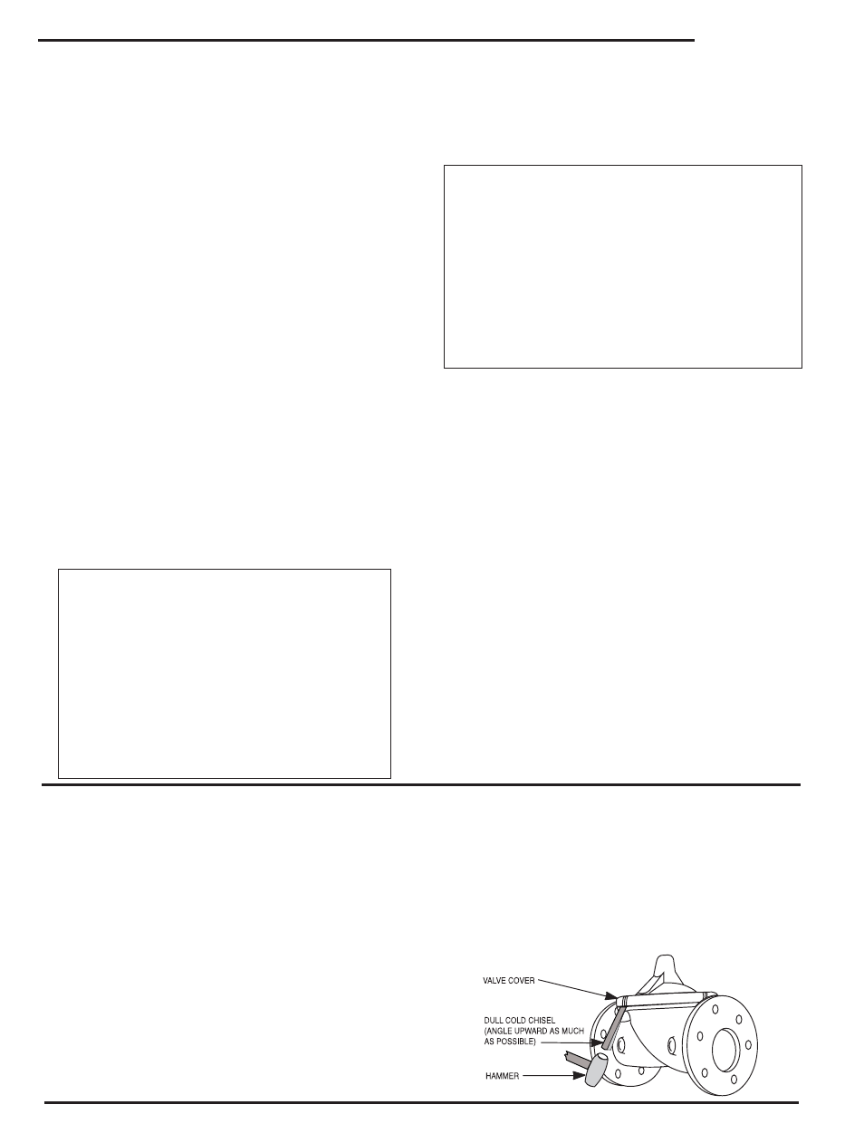
3. Remove cover nuts and remove cover. If the valve has been
in service for any length of time, chances are the cover will have
to be loosened by driving upward along the edge of the cover
with a dull cold chisel.
STEM TRAVEL
(Fully Open to Fully Closed)
Valve Size (inches)
Travel (inches)
Inches
MM
Inches
MM
1 1/4
32
0.4
10
1 1/2
40
0.4
10
2
50
0.6
15
2 1/2
65
0.7
18
3
80
0.8
20
4
100
1.1
28
6
150
1.7
43
8
200
2.3
58
10
250
2.8
71