Fire protection pressure reducing valve, Models, Typical application – Cla-Val 90-21 Technical Manual User Manual
Page 6: Mea ul / ulc listings
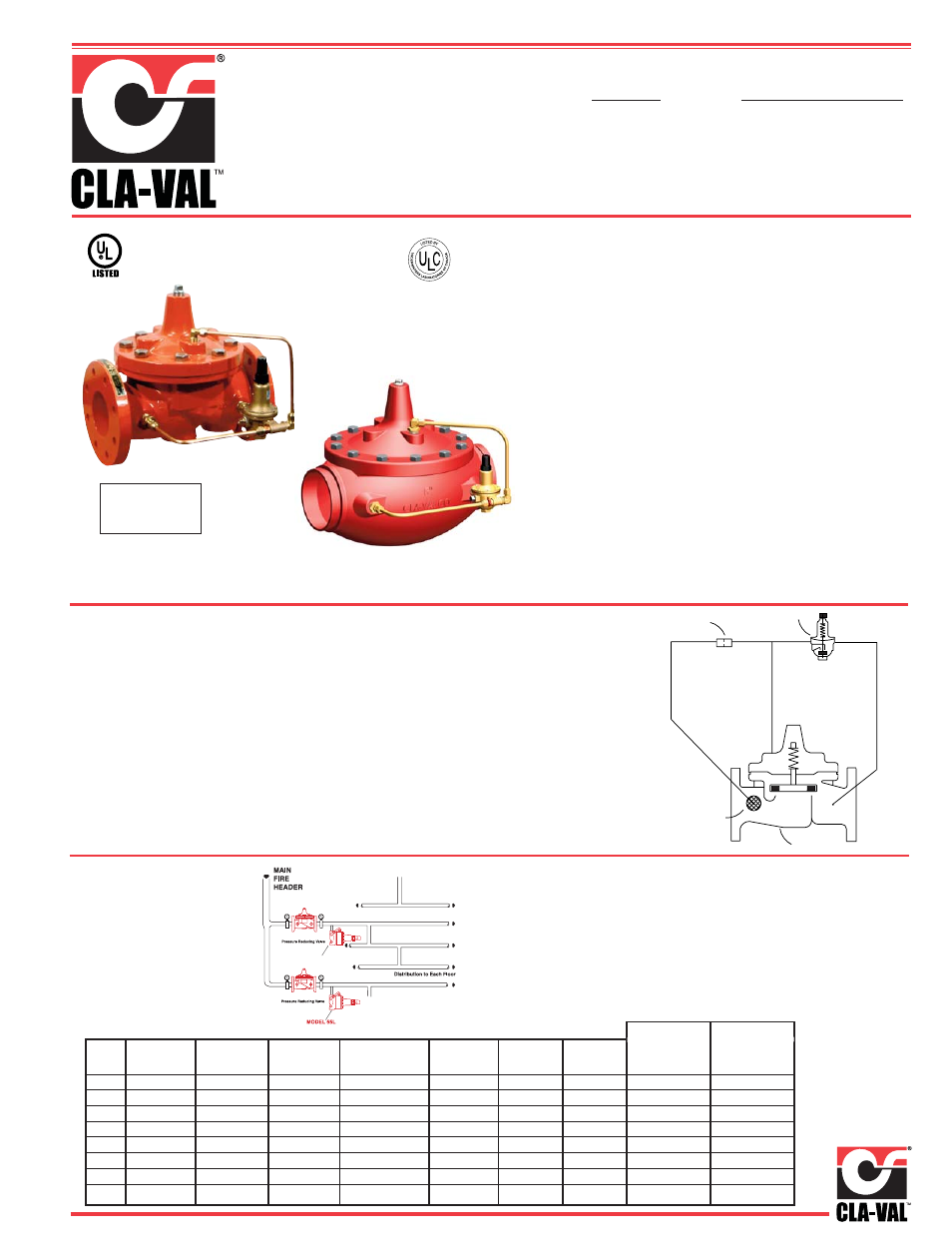
90G-21
90A-21
MODELS
• U.L. Listed, ULC Listed, MEA Approved
• Globe or Angle Pattern
• Proven Reliable Design
• Available in Cast Bronze, Ductile Iron and
Cast Steel
• Accurate Pressure Control
• In Line Service
• Grooved Ends (1 1/2” - 8”)
Cla-Val 90G-21 (globe) and 90A-21 (angle) Pressure Re-
ducing Valves are indispensable in any fire protection sys-
tem. Our diaphragm actuated design is proven highly reliable
and easy to maintain. We offer both a globe or angle pattern
with a full range of adjustments. These valves are also avail-
able in a variety of material options. Epoxy coating is
strongly recommended for all fire system valves (excluding
bronze valves). The 90G-21 and 90A-21 can be supplied
with optional internal and external epoxy coating of the main
valve wetted surfaces.
Special System Water Control Valves – Class II
UL Product Category VLMT – File No. Ex 2534
90-21 UL Listed
Fire Protection Valve
90-21 UL Listed
Grooved End
Fire Protection Valve
INLET
OUTLET
4
1
3
2
Schematic Diagram
Item Description
1 Model 100-01 Hytrol
(Globe or Angle)
2 X58C Restriction Tube Fitting
3 CRD Pressure Reducing Control
4 X46A Flow Clean Strainer
Cla-Val 90G-21 (globe) and 90A-21 (angle) Pressure Re-
ducing Valves automatically reduce a higher inlet pressure
to a steady lower outlet pressure regardless of changing
flow rate and/or varying inlet pressure. The valves pilot con-
trol system is very sensitive to slight downstream pressure
fluctuations, and will automatically open or close to maintain
the desired pressure setting. The downstream pressure can
be set over a wide range by turning the adjustment screw
on the CRD pilot control. The adjustment screw is protected
by a screw-on cover, which can be sealed to discourage
tampering.
Typical Application
Underwriters Laboratories requires the installation of pressure
gauges upstream and downstream of the Pressure Reducing Valve.
Also, a relief valve of not less than 1/2 inch in size must be installed
on the downstream side of the pressure control valve. Adequate
drainage for the relief valve discharge must be provided.
CLA-VAL 90-21
CLA-VAL 90-21
Model 55L
Fire Protection Pressure Reducing Valve
MEA
UL / ULC Listings
Size
1 1/2''
2"
2 1/2"
3''
4"
6"
8"
10"
Ductile Iron
150# F
UL / ULC
UL / ULC
UL / ULC
UL / ULC
UL / ULC
UL / ULC
UL / ULC
ULC
Ductile Iron
300 # F
UL
UL / ULC
UL / ULC
UL / ULC
UL / ULC
UL / ULC
UL/ULC
ULC
Ductile Iron
300# S
UL / ULC
UL / ULC
ULC
UL / ULC
Bronze
300# Threaded
UL / ULC
UL / ULC
UL / ULC
UL / ULC
Bronze
150# F
ULC
ULC
ULC
ULC
Bronze
300# F
ULC
ULC
ULC
ULC
Cast Steel
300# F
UL
UL
UL
UL
UL
Ductile Iron
Grooved End
UL
UL
UL
UL
UL
UL
UL
Ductile Iron
Grooved End
UL
UL
UL
Globe Pattern Angle Pattern