X144 e-flowmeter, Quick start installation & removal instructions, Standard wiring – Cla-Val X144 Quick Manual User Manual
Page 3: Step-by-step x144 e-flowmeter removal instructions, Knurled lock
X144 e-FlowMeter
Quick Start Installation & Removal Instructions
X144
e-Flow Meter
white
b
rown
7
8
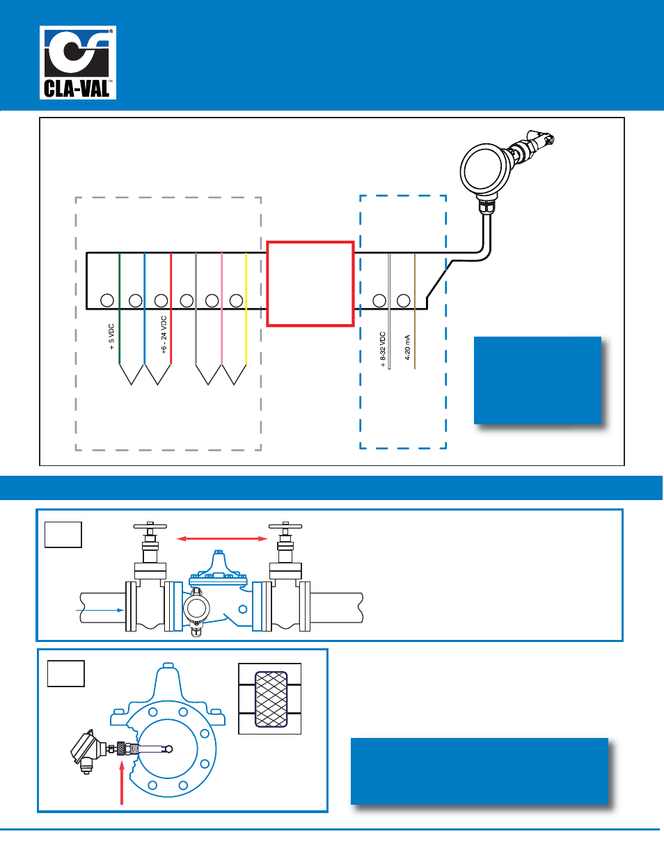
CAUTION:
Do not connect Pulse
Output Circuit and
4-20mA Loop Circuit
simultaneoulsy.
Damage will occur.
Pulse Output
Circuit Wiring
D
ig
ital Pulse
or
Tr
a
n
s
is
to
r
(NPN
) Puls
e
green
b
lue
red
gre
y
p
ink
y
ello
w
1
2
3
4
5
6
+
5VD
C
1.0
A
mi
n
P
ower Suppl
y
-0V (com)
or
6 - 24 VD
C,
1.
0
A
min
.
P
ower
S
uppl
y
4-20mA Loop
Power
Circuit Wiring
Standard Wiring
1
Step-By-Step X144 e-FlowMeter Removal Instructions
CLA-VAL
flow
Isolation Valves
Step 1: Take necessary safety precautions
a) Isolate the control valve
using main line isolation valves
b) Bleed pressure from valve before
removing the e-FlowMeter
c) Disconnect power to all electronic
devices on valve, including e-FlowMeter
2
Knurled
Lock
Step 2: After isolating the valve, bleeding pressure and
disconnecting electronic devices, hand loosen the
Knurled Lock from straight threads
call 800.942.6326 for assistance
or log-on to
www.cla-val.com for more information
for additional
wiring diagrams,
download N-144
IOM Manual at
www.cla-val.com