Cla-val, Description, Material specification – Cla-Val 100-20KO User Manual
Page 4: Application information
100-20KO Hytrol Main Valve with Anti-Cavitation Trim Purchase Specifications
Function
The valve shall be hydraulically operated, single diaphragm actuated, globe pattern. The valve shall consist of three major compo-
nents: the body with seat installed, the cover with bearing installed, and the diaphragm assembly. The diaphragm assembly shall be
the only moving part and shall form a sealed chamber in the upper portion of the valve, separating operating pressure from line pres-
sure. Packing glands and/or stuffing boxes are not permitted and there shall be no pistons operating the main valve or pilot controls.
Ductile Iron is standard, other materials shall be available. No fabrication or welding shall be used in the manufacturing process.
Description
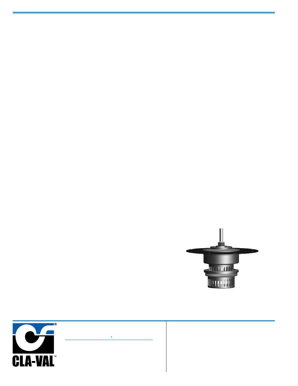
The anti-cavitation features of the seat and disc guide detail shall have flow slots equally spaced around their perimeters. The seat slots shall be
orientated around the perimeter of the seat so that fluid entering the valve shall flow through the seat slot detail such that the fluid flow converges
in the center chamber of the seat allowing potential cavitation to dissipate. The disc guide slots shall be positioned around the perimeter of the
disc guide, configured and oriented in an angular direction so that fluid flow exiting through the slots is diverted away from direct impact into pres-
sure boundary surfaces. Flow exiting the disc guide slots is directed in an angular path to increase the distance between the slot geometry and
pressure boundary surfaces. If cavitation conditions exist, the increased distance between the slots and pressure boundary surfaces minimizes
the potential for damage by allowing the cavitation bubbles to dissipate before they come in contact with pressure boundary surfaces. Anti-cav-
itation characteristics shall be controlled by the described slotted seat and disc guide components. The disc guide shall slide in the seat and allow
controlled flow through the seat slots into the central seat chamber where flow shall continue from the seat chamber and exit through the angu-
larly oriented slots of the disc guide. The seat and disc guide features used together shall provide anti-cavitation characteristics suitable for ap-
plications where a large controlled pressure drop is desired.
The flexible, non-wicking, FDA approved diaphragm shall consist of nylon fabric bonded with synthetic rubber compatible with the op-
erating fluid. The diaphragm must withstand a Mullins burst test of a minimum of 600 psi per layer of nylon fabric and shall be cycle
tested 100,000 times to insure longevity. The diaphragm shall be fully supported in the valve body and cover by machined surfaces
which support no less than one-half of the total surface area of the diaphragm in either the fully open or fully closed position.
The valve seat in eight inch and smaller size valves shall be threaded into the body. Valve seat in ten inch and larger size valves shall
be retained by flat head machine screws for ease of maintenance. The seat shall be of the solid, one-piece design and shall have a
minimum of a five degree taper on the seating surface for positive drip-tight shut-off. Pressed-in bearings and/or multi-piece seats shall
not be permitted.
To insure proper alignment of the valve stem, the valve body and cover shall be machined with a locating lip. No "pinned" covers to
the valve body shall be permitted. All necessary repairs and/or modifications other than replacement of the main valve body shall be
possible without removing the valve from the pipeline.
The valve manufacturer shall warrant the valve to be free of defects in material and workmanship for a period of three years from date
of shipment, provided the valve is installed and used in accordance with all applicable instructions. The valve manufacturer shall be
able to supply a complete line of equipment from 1
1
⁄
4
" through 48" sizes and a complete selection of complementary equipment.
Material Specification
Valve Size:
Pressure Rating:
Main Valve Body and Cover:
Temperature Range:
Main Valve Trim:
Coating:
End Detail:
Desired Options:
Application Information
Inlet/Outlet Pressures:
Flow Rate:
Pipe Diameter:
Function (i.e. - Pressure Reducing, Pressure Relief, etc.):
This valve shall be a Cla-Val Model No. 100-20KO Hytrol Main Valve with
Anti-Cavitation Trim as manufactured by Cla-Val, Newport Beach, CA
Note: Add this Hytrol Anti-Cavitation Trim Purchase Specification to main valve
specification for control valves where there is a high potential for cavitation damage.
Please contact our Regional Sales Offices or Factory for assistance.
PO Box 1325 Newport Beach CA 92659-0325
Phone: 949-722-4800
Fax: 949-548-5441
CLA-VAL
CLA-VAL CANADA
CLA-VAL EUROPE
4687 Christie Drive
Beamsville, Ontario
Canada L0R 1B4
Phone: 905-563-4963
Fax: 905-563-4040
Chemin dés Mesanges 1
CH-1032 Romanel/
Lausanne, Switzerland
Phone: 41-21-643-15-55
Fax: 41-21-643-15-50
©
COPYRIGHT CLA-VAL 2012 Printed in USA
Specifications subject to change without notice.
www.cla-val.com
E-100-20KO (R-01/2013)
Represented By:
The Anti-Cavitation Trim components can be
retrofitted to existing Hytrol valves if the ap-
plication indicates an appropriate need.
Please consult factory for details.
Patented